Slice

Slice Parameters
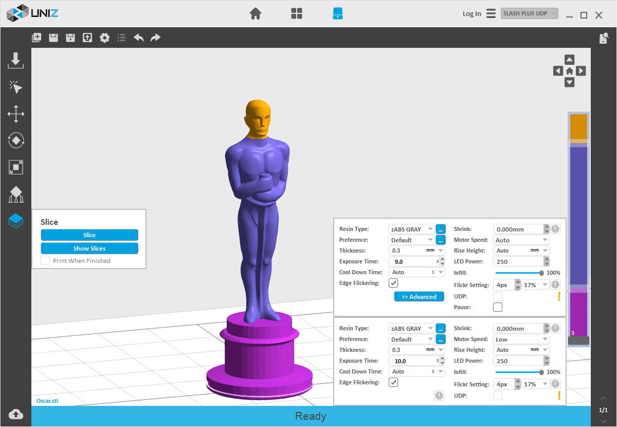
This is customize the slice parameters of each segment of a model.
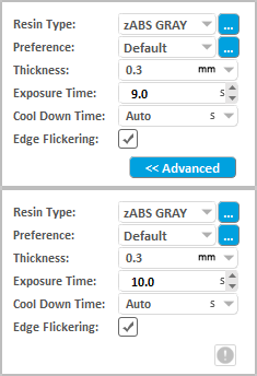
After version 1.2.0 and the upper Desktop sets a separate slider at the third layer by default and users cannot move this slider in the bar. The Exposure Time of the first three layers will be set directly in the slice parameter interface rather than in the advanced settings.
Since 1.3.0 version, "Slice Parameter Settings" has been adding "Preference" and "LED Power", accordingly "LED Power" window will be removed from "Advanced Setting" . Uniz Desktop will no longer memorize the last used "Exposure Time", therefore "Restore Default of Exposure Time" function be abolished. Users You can memorize favorite printing parameters by "Preference".

Resin Type
Resin Type provides different default values for different resin type.
From Ver. 2.0 we added custom resin in the slice setting interface; user can add third part resin setting in the resin list (including layer thickness and default preference, etc.)
For more details, see: Edit 3rd Resin
Preference
Preference: Each resin can define multiple preference to memorize frequently-used printing parameter, including: Layer Thickness, Exposure Time, Cool Down Time, Pixel ContractionShrink, LED Power, Motor Speed, Rise Height, Infill, UDP Mode.
For more details, see: Edit Preference
LED Power
LED Power: Setting the power of the LED module, the range is 0-300, 150-250 is suggested.
Thickness
Thickness is the layer thickness, which is related to Z resolution.
Layer thickness can be customized from 0.01 to 0.5 mm in 2.0 version.
Notice:
1. Three decimal places, the last number can only be 5 or 0.
2. Customized layer thickness doesn't have a default printing parameters.
Exposure Time
Exposure Time is the exposure time of a layer in this segment, it may vary due to different layer thickness setting or different resin types.
When users modify the exposure time and execute slicing function, the system will record the new exposure time and the corresponding layer thickness and modify the suggested exposure time which will be applied during the next printing. Click the "Restore Default" button to use the preset value by the system.
Cool Down Time
Cool Down Time is the time to cool down the exposed layer to protect the polymer film from overheating. For sustained low peel force and prolonged film life, it is recommended to keep the film temperature below 50deg C. Overheating will cause the film to warp, delaminate, or even break.
Cool can be customized from 0.01 to 0.5 mm in 2.0 versions from 0 to 99 seconds. It must be positive integer.
TIP
Avoid exposing the same spot or area over and over, try to orient the model’s walls or pillars in oblique angle so the exposure area changes every next layer.
Edge Flickering
Due to light scattering and free radical diffusion effect, edges of printed model tends to be larger than theoretical model. Using a lower exposure dosage may correct the diffusion at the risk of lowering printing success rate. In order to compensate diffusion effect with correct dosage, the "Edge Flickering" option is added to the Slice Parameters Interface.
For more details, see: Edge Flickering
Flickr Setting
Edge Flickering will be displayed on LCD panel during exposure of each layer, the accuracy of flickering setting relies on pixel flickered and percentage of edge exposure dosage.
For more details, see: Edge Flickering
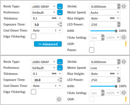
Pressing the "Advanced" Button will open following sub menu

Pixel Shrink
Pixel Shrink: Shrink or expand the slice polygons.
For more details, see: Slice Shrink Setting
Motor Speed
Motor Speed defines the speed of electric motor that controls the peel motion of the platform.
Raise height
Rise Height defines the travel height of the peel motion.
Raise height can be customized from 0.01 to 0.5 mm in 2.0 versions from 0 to 15 seconds. It must be positive integer.
Infill
Infill:You can drag the slider horizontally to modify the infill ratio ranging from 0% to 100%. The model will be:
- hollowed but not filled when the ratio is 0%;
- hollowed and filled by the ratio when the ratio is among 10% to 90%;
- filled but not hollowed when the ratio is 100%;
Please view Advanced Settings for the hollowing wall thickness and infill type.
UDP model
Users need to check this box when printing UDP model. UDP mode can only be used when the following requirements are met:
- 1. A printer with UDP mode support is connected and selected in the interface, such as SLASH PLUS UDP;
- 2. UDP resin is loaded and the corresponding resin type is selected in the interface, such as zUDP ORANGE;
- 3. A slice thickness supporting UDP mode is selected, such as 0.100mm.;
The Cool Down Time, the Motor Speed, the Rise Height and LED Power will apply the default value set when UDP is checked.
Pause
Pause sets a pre-set pause at the layer of choice during printing, the pause can be resumed after pressing the Resume Button in the printing control tab.
Customize Your Own Z Resolution
Dividing the model into multiple segments and define different slice parameters, Z resolution customization can be used to balance print speed and surface quality.
Click the block on the slider bar to start customizing print parameters. The white line shows the division layer of the two adjacent segments. The upper menu sets the segment above the division, and the lower menu sets the segment below. You may drag the slider block to change the division location or double click on blank space on the slider bar to add another division layer. Press Delete key when dragging the slider block to erase the division layer. The last division layer cannot be deleted.
Double click the selected slider and you get a text box. Type layer in the text box and then press ENTER key to finish and close the editing.
Note: The value must be between the upper and lower segments.
Click the "+" Key to move the slider upward for one layer till to the top of the slider or the next layer of the up slider.
Click the "-" Key to move the slider downward for one layer till to the previous layer of the down slider.
Notice: The slider at the bottom (the third layer) does not support operation by the +/- button.
Click the "PageUp" Key to select the separate slider above.
Click the "PageDown" Key to select the separate slider above.
-
Slice Tools
Click Slice Button to slice all models on the build platform with the defined parameters. The estimated print information will show in the status bar.

Click Show Slices Button to check slice of any sliced layer.

Click the 2D/3D button at the top right corner to shift the windows between 2D and 3D.Input layer number in the top right box to check the corresponding sliced layer information.
Drag the right slider vertically to view each layer.
Click the Up/Down arrow to view the previous/next layer.
If Print When Finished is checked, the sliced data will be sent to the selected printer in the right bar automatically, you still need to touch the front button on the printer to confirm the print job to start printing.
TIP
"Print When Finished" will only be enabled when a printer is connected, the corresponding Printer Control Panel is open, and the printer is in ready status.
The Previous Articles
- Design Specification
- Installation & Setup
- Printer Network
- Activate the Printer
- Trial and Trial Expiration
- Upgrade the Printer License
- Upgrade the Printer Firmware
- Remote Monitoring
- Accessory replacing remind and timer reset
- Store
- library
- Set Up Your Print
- One Click Print
- Generate Support
- Slice
- Print Tools
- Edit 3rd Resin
- Edit Preference
- Additional Tools


