Design Specification
A well-designed model marks the beginning of a good project. The purpose of this design guide is to help users maximize the effectiveness of their Uniz products by optimizing their 3D models prior to printing. This guide provides tips and tricks to work around geometric limitations and avoid unsuccessful prints.
Note that the following information pertains to Uniz printers using zUDP or zABS resins, and the default layer thickness of 100 microns. Results may slightly vary when printing with higher or lower layer thickness.
Design Specification- UDP Printing Mode
Suitable Models For UDP Printing

Due to physical limitations, models with solid cross-sections cannot be printed with UDP mode. Fully enclosed shapes will also start producing problems past a certain height. Hollow objects with a vertical release slot are recommended. For models that require solid infill, natural peel mode is recommended.
Note: Tall enclosed structures would impose a complicated resin level effect and cause deteriorated inner surface and eventually damage the wall, resulting in unwanted thin walls or holes, this applies to all top-down continuous SLA technologies. For any enclosed structures, resin inside will be trapped since the structure wall forbid resin from flowing into or out of the wall. To build the walls continuously, UDP mode consumes resin from both inside and outside of the wall. The resin level inside will drop significantly faster than outside and depletes quickly. Once depleted, the walls will be broken either by insufficient inside resin or by the pressure from outside resin (if the outside resin level is high). Solutions are: avoid fully enclosed structures, periodic release holes in the vertical direction, or vertical release slots.
Maximum Printing Height For Continuous Printing In The Same Spot
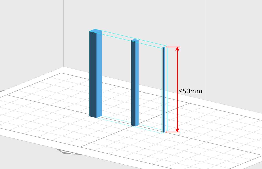
To prevent overheating the separation film, printing on the same location on the build platform for over a 50mm height should be avoided. Always tilt by a small angle when printing long models and supports.
Maximum Joined Wall Thickness
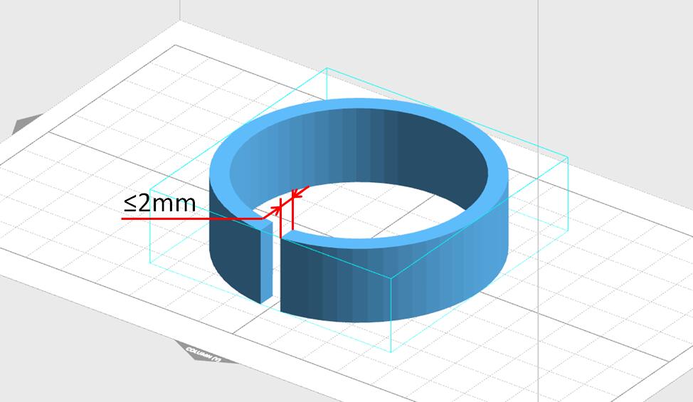
Thicker walls require more time for resin to flow across underneath. A wall thickness over 2mm is not recommended.
Design Specification- UDP and Natural Peel Mode
Minimum Supported Wall Thickness
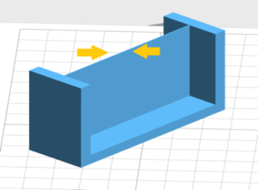
Recommended: 1.0 mm
A supported wall is a wall that is supported on more than two sides. The minimum supported wall thickness is 1.0mm.
Minimum Unsupported Wall Thickness
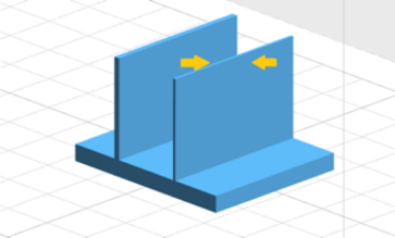
Recommended: 0.6mm
An unsupported wall is a structure that is connected to other walls on fewer than two sides. An unsupported wall that is thinner than 0.6 mm may warp or detach from the model during printing.
Maximum Unsupported Overhang Length
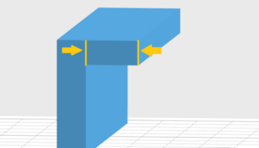
Recommended: 1.0 mm
An overhang refers to the part of the model that sticks out parallel to the build platform. Printing overhangs without supports is not advised since the layers cannot maintain their structure. Horizontal overhangs will be distorted and will become increasingly deformed as the length of the overhang increases.
Minimum Unsupported Overhang Angle
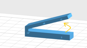
Recommended: 19° from horizontal plane (35 mm long × 10 mm wide × 3 mm thick)
The overhang angle refers to the angle between the horizontal and the overhang. Printing at an angle less than 19° could cause the overhang to break off the model during the peel process. It is best to rotate the model so that flat surfaces can be held up by supports if they are not already self-supported.
Maximum Horizontal Support Span/Bridge
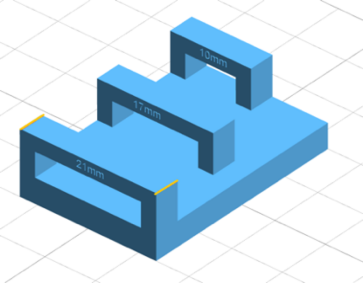
Recommended: 21 mm (5 mm width × 3 mm thick)
A span is the distance between two intermediate supports of a structure. While printing horizontal spans is generally not advised, certain geometries
may work. For 5mm and 3mm wide beams, spans longer than 21mm are likely
to fail. Wider beams must be kept shorter to avoid breaking during the peeling process.
Minimum Vertical-Wire Diameter
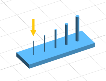
Recommended: 0.3 mm (7 mm tall) to 1.5 mm (30 mm tall)
A wire is a feature which has its height greater than two times its width. The
ratio of width to height can help determine if the structure is stable: At 0.3mm width the structure can go up to 7mm height before distortions. 1.5mm width wires can go up to 30mm without defects.
NOTE: Similar to washing thin walls, extra care should be taken when washing small wires, as they are weakened by IPA and can be easily be damaged. Minimizing the time the part is immersed in IPA will limit this risk.
Minimum Embossed Detail
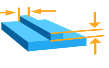
Embossed details are shallow raised up features on your models, such as text or patterns. Details smaller than 0.1 mm in thickness and in height may not be visible on your print.
Minimum Engraved Detail
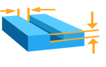
Recommended: 0.4 mm
Engraved details are imprinted or recessed features on your models. Details recessed less than 0.4 mm in thickness and in height may not be visible on your print because they may fuse together with other parts of the model during exposure.
Minimum Clearance
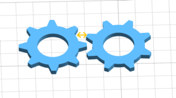
Recommended: 0.5 mm
Clearance is the amount of distance needed between two moving parts of a model (e.g., the distance between gears or joints). A clearance smaller than 0.5mm may cause parts to fuse together as well.
Minimum Hole Diameter
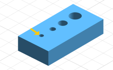
Recommended: 0.5 mm
Holes with a diameter less than 0.5 mm in the x, y, and z axes may close off during printing due to fusing effect.
Minimum Drain Hole Diameter
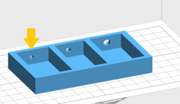
Recommended: 0.5 mm
Drain holes are recommended for UDP mode as well as natural peel mode for resin to escape in models that are a fully enclosed cavity (like a hollow sphere or hollow cylinder printed directly on the build platform). Without drain holes of at least 3.5 mm in diameter, the part may trap resin and lead to unwanted deformation of the print.
In This Article
- Suitable Models For UDP Printing

- Maximum Printing Height For Continuous Frinting In The Same Spot

- Maximum Joined Wall Thickness

- Minimum Supported Wall Thickness

- Minimum Unsupported Wall Thickness

- Maximum Unsupported Overhang Length

- Minimum Unsupported Overhang Angle

- Maximum Horizontal Support Span/Bridge

- Minimum Vertical-Wire Diameter

- Minimum Embossed Detail

- Minimum Engraved Detail

- Minimum Clearance

- Minimum Hole Diameter

- Minimum Drain Hole Diameter

For UDP Mode
For Natural Peel Mode
The Previous Articles
- Design Specification
- Installation & Setup
- Printer Network
- Activate the Printer
- Trial and Trial Expiration
- Upgrade the Printer License
- Upgrade the Printer Firmware
- Remote Monitoring
- Accessory replacing remind and timer reset
- Store
- library
- Set Up Your Print
- One Click Print
- Generate Support
- Slice
- Print Tools
- Edit 3rd Resin
- Edit Preference
- Additional Tools

