Using UNIZ Industry
This article applies to NBEE , NBEE H, SLASH 2 PLUS
1.Software introduction
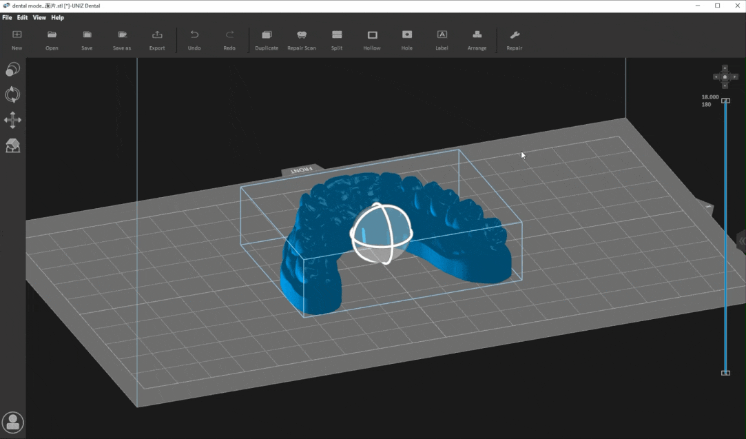
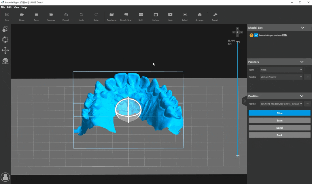
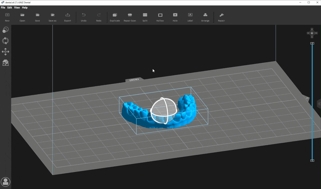
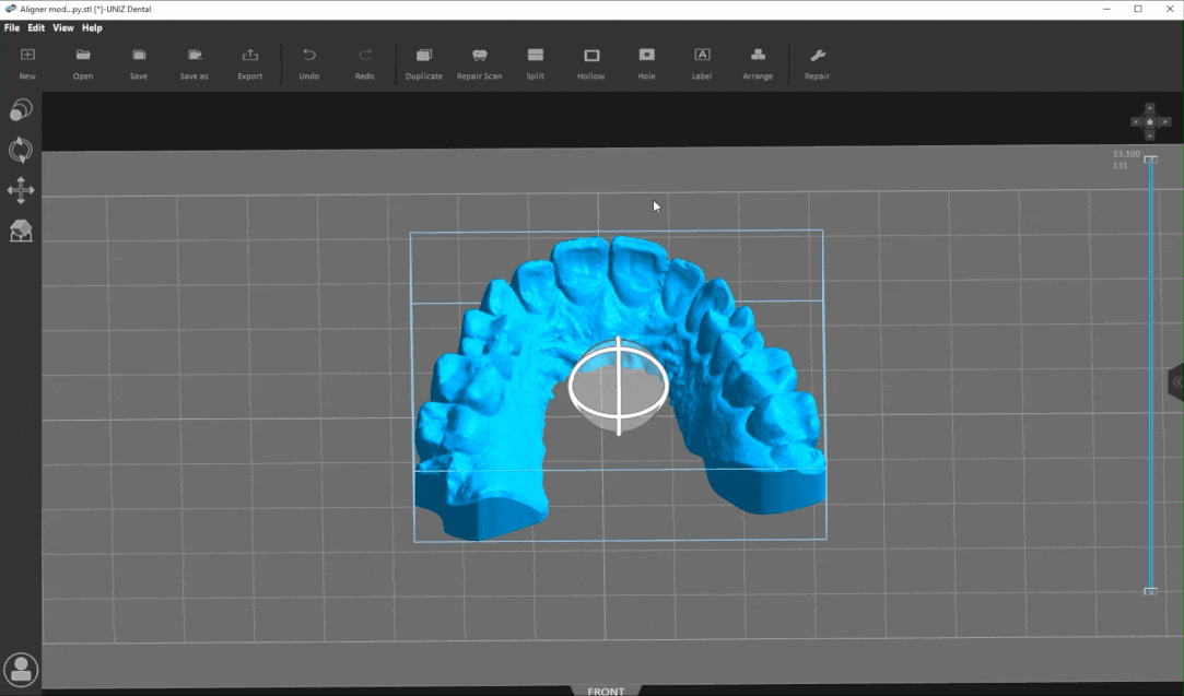
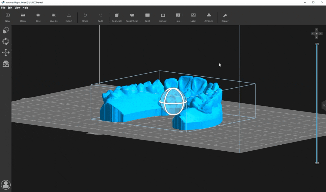
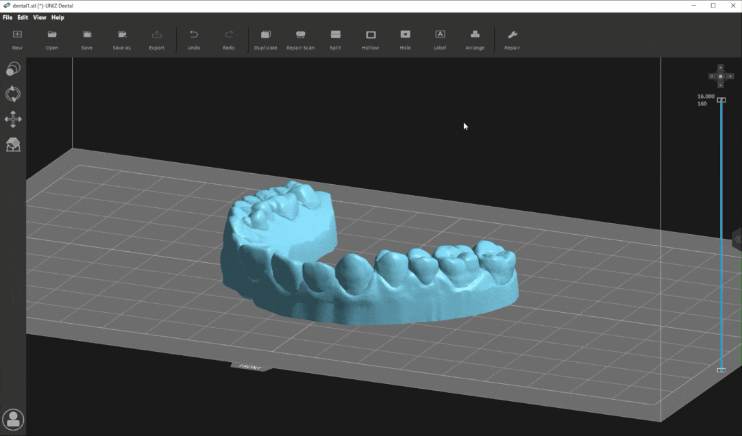
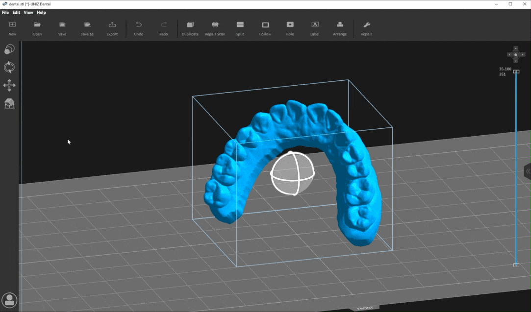
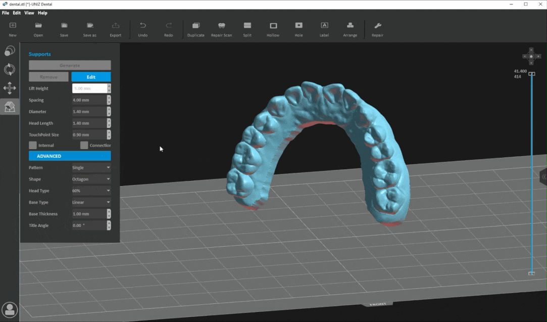
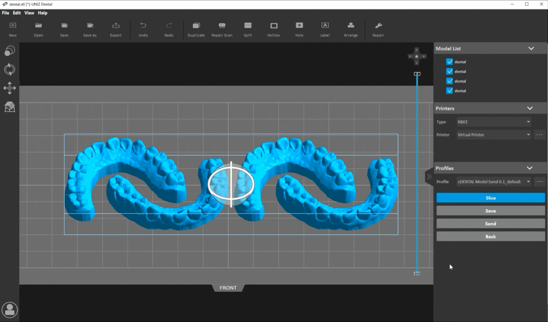
UNIZ Industry is a slicing software designed especially for Industrial 3D printer of UNIZ. In addition to common functions such as loading, rotation, generating supports, slicing ,UNIZ Industry provides many professional Industrial tools including Repair Scan, Split, Hollow, Hole, Label and Arrange. The following picture shows the interface of the software.
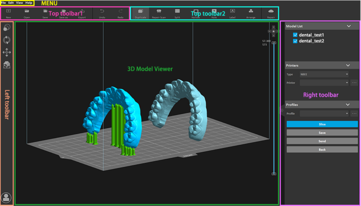
There are five parts in the interface.
1.1.Menu
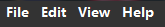
- File: Create, open and save projects, load and export models,load examples models.
- Edit: Undo/redo operations;size, rotation, position, supports;select all, deselect all, duplicate selected, delete selected;and Mirror X selected、Mirror Y selected、Mirror Z selected.
- View: Switch different views of your model; show or hide the model manipulator, toolbar, and right toolbar, switch software display languages: English, simplified Chinese,Spanish and Russian.
- Help: View software information ,Online help, release notes, and allow you to check for updates.
1.2.Top toolbar
1.2.1.Top toolbar1
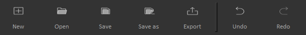
- New : Create a new project(zprj).
- Open: To open 3D model or slices. The supported file formats are: stl, obj, 3mf, amf, zprj, slc, zslr.
- Save : Save the loaded model as a project file (zprj).
- Save as: Save the loaded model to another project file (zprj).
- Export: Export selected models and its support to STL format.
- Undo: Repeal one previous operation.
- Redo: Remake one previous operation repealed by "Undo".
1.2.2.Top toolbar 2
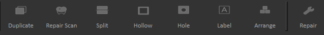
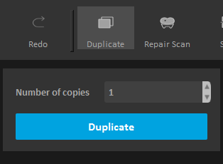
- Duplicate: Copy the selected models. The number of copies can be set by yourself.
- Repair Scan: Repair the scan dental data into a printable dental model.
- Split: Divide the selected model into two parts according to the plane and position.
- Hollow: Hollow out the selected solid models.
- Hole: Dig holes on the selected models.
- Label: Mark text on the surface of the selected models.
- Arrange: Arrange all loaded models. Or Arrange all dental models horizontally or vertically.
- Repair: Repair the selected models with abnormal topology.
1.3.Left toolbar
 Size: Modify the size of the selected model./li>
 Rotation: Change the orientation of the selected model.
 Position: Edit the position of the model, center, and duplicate the selected model, and automatically arrange the models.
 Supports: Generate supports manually or automatically.
 Login: Users can login the software by using the account registered on the official website.
1.4.Right toolbar
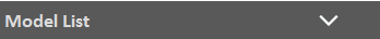
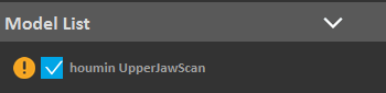
Model List: View the loaded model, modify the visibility and state of the selected model, and operate the models in other ways such as To platform、Centered、Duplicate、Mirror X、Mirror Y、Mirror Z, and deleting the selected model.If the model is defective, exclamation mark will show.
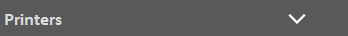
Printers: Select the printer type to automatically select the printers of this type that have been connected. Manage your printer in LAN: Obtain printers in LAN automatically or manually; Delete printers that are not in LAN. Different types printers have different printing size and accuracy.

Profiles: select a preset slice profile; Manage customized printing profile; Slice loaded models, save slice to disk , send slice file to current printer. Different printers have different profiles.

Show/Hide: Click it to show or hide the toolbar on the right to make the "3D Model Viewer" wider.
1.5 3D Model Viewer
The interactive window is composed of three parts: the operation area in the middle, the view switch on the upper right corner, and the profile viewer on the right.
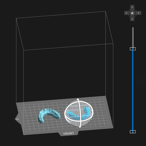
1.5.1.Operating Area
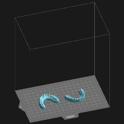
- Scope: The cube identifies the printing size and scope of the 3D printer. If the model is out of range, the excess part will be marked in red.
- Grid: The grid length and width are both 10mm, which is convenient for users to quickly evaluate the size and position of the model.
- Coordinate system: The coordinate origin of the 3D scene coordinate system is the grid center.
- X:X means the X axis.
- FRONT: Point to the front of the printer
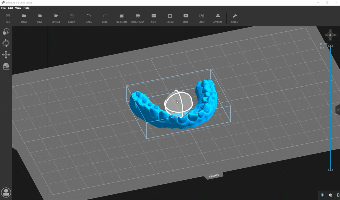
1.5.2.Manipulators
Select one or more models, manipulators will show on the model. Press the circle on the manipulator to drag and release, the model will rotate around the corresponding axis.

 Operating circle: Click and press the circle on the manipulator to drag and release, the model will rotate around the corresponding axis.
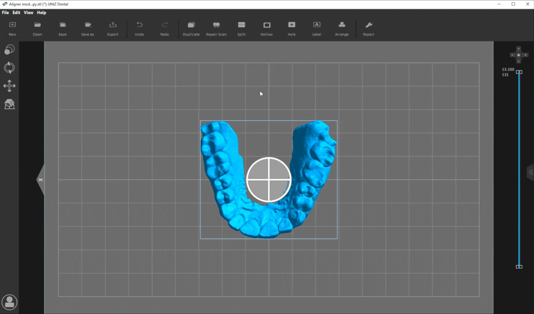
1.5.3.View Switch
Switch the different view of the model.

 Left view
 Top View
 Right view
 Front view
 Main view
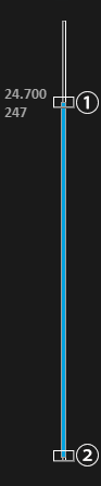
1.5.4.Slice Viewer
Drag the upper slider to cut the upper part of the model and observe the section; Drag the lower slider to cut the lower part of the model and observe the section. The left side of the slider shows the current height and number of layers.

Upper slider 、Lower slider
2.Operate introduction
2.1.Normal operation
Selected toolbar:Select the target toolbar by clicking the left mouse button
Selected model:
- 1)In the "3D Model Viewer",clicking the left mouse button to selected single model or long pressing the mouse box to selected multiple models.
- 2)In the "File List", clicking the left mouse button to selected single model name or long pressing the mouse box to select multiple model names.
Unselect the model:
- 1)In the "3D Model Viewer", click anywhere except the model to deselect the model.
- 2)In the "File List", click anywhere except the model names to deselect the model.
Use the shortcut menu bar:
- 1)In the "3D Model Viewer", display the shortcut menu bar by right mouse click on the selected model.
- 2)In the "File List",display the shortcut menu bar by right mouse click on the selected model names.
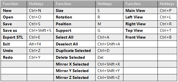
2.2.Hotkeys
3.Printing process
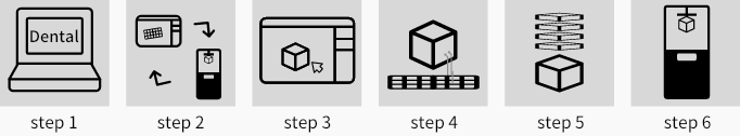
- Step 1:Open Uniz
The landscape will show more detailson your computer.
Using UNIZ Industry
This article applies to NBEE , NBEE H, SLASH 2 PLUS
1.Software introduction
UNIZ Industry is a slicing software designed especially for Dental 3D printer of UNIZ. In addition to common functions such as loading, rotation, generating supports, slicing ,UNIZ Industry provides many professional dental tools including Repair Scan, Split, Hollow, Hole, Label and Arrange. The following picture shows the interface of the software.
There are five parts in the interface.
1.1.Menu
- File: Create, open and save projects, load and export models,load examples models.
- Edit: Undo/redo operations;size, rotation, position, supports;select all, deselect all, duplicate selected, delete selected;and Mirror X selected、Mirror Y selected、Mirror Z selected.
- View: Switch different views of your model; show or hide the model manipulator, toolbar, and right toolbar, switch software display languages: English, simplified Chinese,Spanish and Russian.
- Help: View software information ,Online help, release notes, and allow you to check for updates.
1.2.Top toolbar
1.2.1.Top toolbar1
- New : Create a new project(zprj).
- Open: To open 3D model or slices. The supported file formats are: stl, obj, 3mf, amf, zprj, slc, zslr.
- Save : Save the loaded model as a project file (zprj).
- Save as: Save the loaded model to another project file (zprj).
- Export: Export selected models and its support to STL format.
- Undo: Repeal one previous operation.
- Redo: Remake one previous operation repealed by "Undo".
1.2.2.Top toolbar 2
- Duplicate: Copy the selected models. The number of copies can be set by yourself.
- Repair Scan: Repair the scan dental data into a printable dental model.
- Split: Divide the selected model into two parts according to the plane and position.
- Hollow: Hollow out the selected solid models.
- Hole: Dig holes on the selected models.
- Label: Mark text on the surface of the selected models.
- Arrange: Arrange all loaded models. Or Arrange all dental models horizontally or vertically.
- Repair: Repair the selected models with abnormal topology.
1.3.Left toolbar
- Size: Modify the size of the selected model./li>
- Rotation: Change the orientation of the selected model.
- Position: Edit the position of the model, center, and duplicate the selected model, and automatically arrange the models.
- Supports: Generate supports manually or automatically.
- Login: Users can login the software by using the account registered on the official website.
1.4.Right toolbar
Model List: View the loaded model, modify the visibility and state of the selected model, and operate the models in other ways such as To platform、Centered、Duplicate、Mirror X、Mirror Y、Mirror Z, and deleting the selected model.If the model is defective, exclamation mark will show.
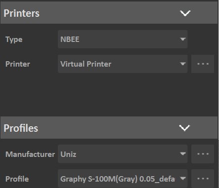
Printers: Select the printer type to automatically select the printers of this type that have been connected. Manage your printer in LAN: Obtain printers in LAN automatically or manually; Delete printers that are not in LAN. Different types printers have different printing size and accuracy.
Profiles: select a preset slice profile; Manage customized printing profile; Slice loaded models, save slice to disk , send slice file to current printer. Different printers have different profiles.
Show/Hide: Click it to show or hide the toolbar on the right to make the "3D Model Viewer" wider.
1.5 3D Model Viewer
The interactive window is composed of three parts: the operation area in the middle, the view switch on the upper right corner, and the profile viewer on the right.
1.5.1.Operating Area
- Scope: The cube identifies the printing size and scope of the 3D printer. If the model is out of range, the excess part will be marked in red.
- Grid: The grid length and width are both 10mm, which is convenient for users to quickly evaluate the size and position of the model.
- Coordinate system: The coordinate origin of the 3D scene coordinate system is the grid center.
- X:X means the X axis.
- FRONT: Point to the front of the printer
1.5.2.Manipulators
Select one or more models, manipulators will show on the model. Press the circle on the manipulator to drag and release, the model will rotate around the corresponding axis.
Operating circle: Click and press the circle on the manipulator to drag and release, the model will rotate around the corresponding axis.1.5.3.View Switch
Switch the different view of the model.
Left viewTop View Right viewFront viewMain view1.5.4.Slice Viewer
Drag the upper slider to cut the upper part of the model and observe the section; Drag the lower slider to cut the lower part of the model and observe the section. The left side of the slider shows the current height and number of layers.
Upper slider 、Lower slider
2.Operate introduction
2.1.Normal operation
Selected toolbar:Select the target toolbar by clicking the left mouse button
Selected model:
- 1)In the "3D Model Viewer",clicking the left mouse button to selected single model or long pressing the mouse box to selected multiple models.
- 2)In the "File List", clicking the left mouse button to selected single model name or long pressing the mouse box to select multiple model names.
Unselect the model:
- 1)In the "3D Model Viewer", click anywhere except the model to deselect the model.
- 2)In the "File List", click anywhere except the model names to deselect the model.
Use the shortcut menu bar:
- 1)In the "3D Model Viewer", display the shortcut menu bar by right mouse click on the selected model.
- 2)In the "File List",display the shortcut menu bar by right mouse click on the selected model names.
2.2.Hotkeys
3.Printing process
- Step 1:Open UNIZ Industry on your computer.
- Step 2:Select a printer under the corresponding type. If you do not select, the printer type used last time will be recorded by default (when the software is opened for the first time, the default value of printer type will be displayed).
- Step 3:load the 3D model.
- Step 4:Use the appropriate tool to edit the model.
- Step 5:Set the printing parameters then slice.
- Step 6:Send the slice files to the printer through the U disk or use the network sending function, then start the print;
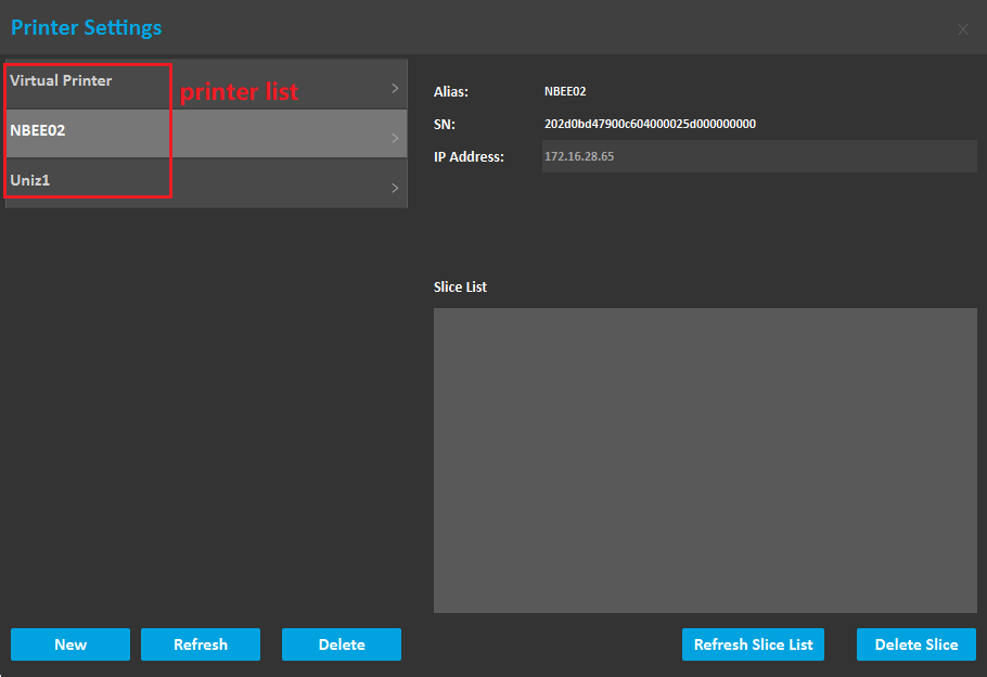
4.Printer Settings
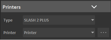
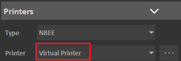
This function mainly manages the printer type and printer list under the currently selected printer type. The printer list includes a virtual printer and real printers. Here is mainly to manage real printers, including automatically searching for printers in the LAN, manually adding printers in the LAN, deleting printers, and managing printer history slices.
4.1.Select Printer Type
Select a printer type, the software will automatically select the printer that have been added of that type.
4.2.Select Printer
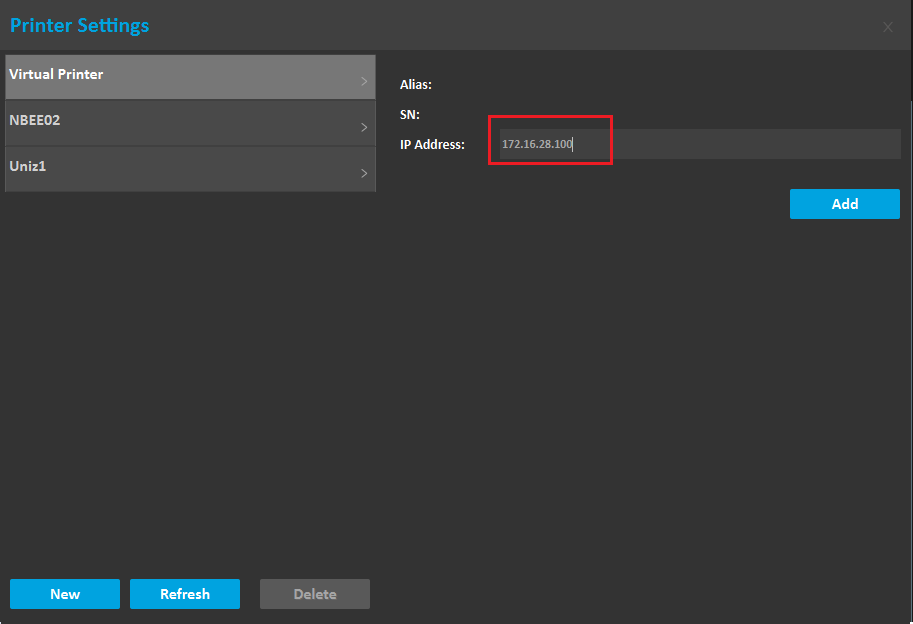
Select a printer in Printer List. If there is no printer currently available, you can choose a Virtual Printer in the list. Virtual Printer is included in the printer list of each printer type. If you do not need to transfer slices based on LAN, select a virtual printer and then perform printing data preparation.
4.3.Add printer
Preconditions:
1)Turn on your printer and make sure it is connected to the network via Ethernet or Wi-Fi.
2)Ensure the printer is connected to the same network as the PC.
If you need to transfer slices to the printer based on LAN, you need to add the printer to the printer list. The software provides two methods: Auto Search and Add Manually.
4.4.Auto Search
1)Click the Button "..." after the Printer List Combox on the right Tools to open the printer settings box.
2) Click the "Refresh" button to automatically search for connected printers and add them to the list.
Note: Due to the network environment, there is a probability that the printer cannot be searched. In this case, it is recommended to add the printer manually.
4.5.Add Manually
1)You need to obtain the printer's IP address on the printer's touch screen.
2)Open the printer settings dialog box, click the "New" button, enter the IP address, and click the "Add" button.
3)If the printer is successfully detected, it will be added to Printer list. If you cannot connect to the target printer, please check the network settings.
Note: A new printer cannot be created when the software is in search.
4.6.Delete printer
Historical printer information is stored in the printer list. If there is an invalid printer in the list, you can delete it in the printer management; open the printer settings dialog box, select the printer, click the delete button, and confirm as prompted.
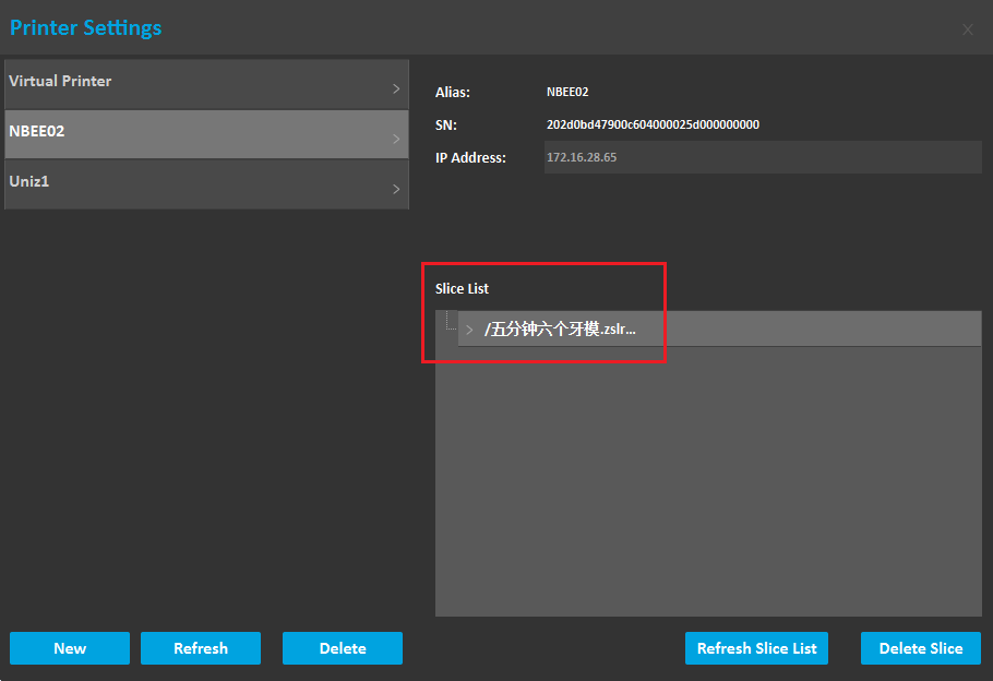
4.7.Manage printer's history slices
Show Slice List: In the printer settings box, select a printer and click the "Refresh Slices" button. The historical slices stored on the selected printer will be listed.
Delete Slice: Select a slice and click "Delete slice" to delete the selected slice.
5.Model management
To open 3D model or slices. UNIZ Industry supported file formats are: stl, obj, 3mf, amf, zprj, slc, zslr.
5.1.Open the model
- Method1:Hold down the left mouse button and drag one or more models into the Dental software icon on your desktop.
- Method2:Hold down the left mouse button and drag one or more models into the "3D Interactive window", and then Release the mouse and wait for the model to load to the view interface.
- Method3:Click the open button in Top toolbar1, and then select the model you want to load when the dialog box opens, finally, click "OK" and wait for the model to load into the "3D Interactive Window".
- Method4:In the menu bar, click "File" and the menu will pop up Then click "Open", and then select the model you want to load when the dialog box opens, finally, click "OK" and wait for the model to be loaded into the "3D Interactive Window".
5.2.Remove the model
- Method1:Click the right mouse button on the selected model to display the shortcut menu bar, and then selected model is deleted after clicking "Delete".
- Method2: Click "Model List" in the Right Toolbar to check all model names, After selecting the model, click the right mouse button to display the shortcut menu bar and then click Delete.
- Method3:Select the model or its name that you want to delete and then press the “delete” key on the keyboard.
5.3.Save the model
- Method1:In the menu bar, click "File" and the menu will pop up, and then click "Save" or" Save as "or" Export STL" , and then Save File window is displayed. Select a location to save the file.
- Method2:In the Top toolbar1,Click "Save" or " Save as " or " Export STL", and then Save File window is displayed and then Select a location to save the file.
6.Modify size
- Method1:Once the Size tab is open, the activated object can be scaled freely by holding the left mouse button on the object and moving the mouse.
- Method2: The activated object can also be scaled by inputting X/Y/Z values in the field. Press Enter to apply changes. Users can also click the up and down button to change the size. The object will scale uniform in Uniform Scaling mode.
- Method3:Modified scale,If a single model is selected, the model will be scaled according to the modified scale; if multiple models are selected, the scale of all models will be set to 1, and the modified scale will be scaled relative to 1.
- Method4:Units,toggle between millimeters and inches.
- Notes:Changing an object's size will break previously generated supports and you will need to redo these.
7.Moving model
7.1.Change Orientation
Models need to be adjusted the angle according to its characteristics to obtain better printing results.
- Method1:Change the values of x, y, and z angles on the Rotation tool dialog, the selected model Angle will be changed.
- Method2:Select the model, the manipulators will be suspended on the model, and then hover the mouse over the single ring of the selected model, finally, Long press the mouse and drag the ring to rotate the model along the axis of the ring.
- Method3: Press the " Align bottom Plane" button in the toolbar, and then Click on the target bottom plane of the model with the mouse and rotate the model quickly.
Notes:
Rotating a model along the X- or Y-axis supports will be removed.
Rotating a model along the Z-axis supports will not be removed.
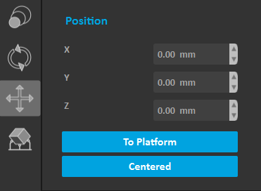
7.2.Change Position
- Method1:The selected model is moved by changing the X/Y/Z values on the Position tool dialog. Click the "To Platform" button to modify the Z value of the selected model to zero, and the model will contact with platform. Click the "Center" button to move the selected model to the center of the XY plane.
- Method2:Manipulators will be suspended on the model, and then click and press selected model,,drag to the target location to release.
- Method3: Click the right mouse button on the selected model to display the shortcut menu bar. Click the "To Platform" button to modify the Z value of the selected model to zero, and the model will contact with platform. Click the "Center" button to move the selected model to the center of the XY plane.
- Method4: Click "Model List" in the Right Toolbar to see all model names, After selecting the model, click the right mouse button to display the shortcut menu bar. Click the "To Platform" button to modify the Z value of the selected model to zero, and the model will contact with platform. Click the "Center" button to move the selected model to the center of the XY plane.
Notes:
If the model has supports, modify the Z value and the supports will be removed.
8.Switch View
8.1.Facade
Changing the Angle of the model makes it easier to rotate, place, and add support.
- Method1:Click the direction button in the view toolbar, the model will show its "Main View" or "Left view" or "right view" or "Top view" or "Front view".

- Method2:Press the right mouse button in the 3D window and drag it. If there is a selected model, the 3D scene will rotate around the center of the selected model. If no model is selected, it will rotate around the tray. If you press the Shift key while dragging the mouse, the view will pan with the drag of the mouse. Scroll the middle mouse button, and the 3D scene will zoom in and out.
- Method3:In the menu bar, click " View " and the menu will pop up, and then click the menu "Main View" / "Left View" / "Right View" / "Top View" / "Front View" to quickly switch the view.
- Method4:Slide the scroll wheel to zoom in or out of the view when the mouse is in the operating area.
8.2.Section view
When using the functions of hollowing, punching, adding support and slicing, check whether the interior of the model meets the printing standards.
Operating Method: Drag the upper slider to hide the upper part of the model and observe the section. Drag the lower slider to hide the lower part of the model and observe the section.
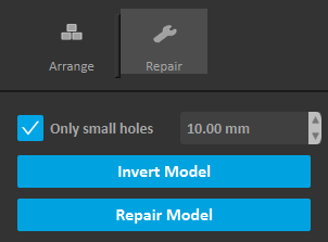
9.Repair
If the 3D model is damaged , the system will prompt user whether to repair,an exclamation point will appear in front of the item in Model List view. If the user chooses to ignore it, the model may fail to print. If the 3D model is defective, an exclamation point will appear in front of the item in Model List view.
Operating Method:
1)If there are some errors in the 3D model data, Click the "Repair Model" button, and the software will automatically repair the model. If the repair fails, a message indicating failure is displayed. If Only small holes is checked, the repair speed will be greatly improved when there are large holes that cannot be repaired.
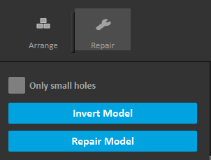
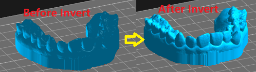
2)The external surface of a normal model is bright blue, if the external surface of the model is dark blue, it means that the surface of the model is inverted, click " Invert " to repair the model.
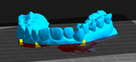
10.Repair Scan
The repair scan tool allows for repairing the intraoral models. It exceeds the functionality of the basic repair tool by adding a basing function, making your model much easier to print and much more aesthetically pleasing.
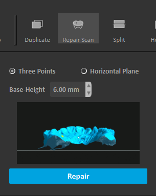
10.1.Three Points
Adjust the base-height in "Repair Scan" box. Pick three points with the left mouse on the model surface to determine the cutting plane, the part that needs to be deleted will be marked in red by default. If the default selection is incorrect, please click the part to be deleted with left mouse. Click the "Repair" button selected model will automatically repair and complete the missing base..
10.2.Horizontal Plane
- Method1:Position the occlusal surface to face away from the build platform. Adjust the z value of the cut plane and base-height in the "Repair Scan" box. Click the "Repair" button selected model will automatically repair and complete the missing base.
- Method2:Position the occlusal surface to face away from the build platform. Adjust the base-height in "Repair Scan" box. Move the mouse to adjust the z value of the cut plane. Click the left mouse button to apply, the selected model will automatically repair and complete the missing base.
- Parameters:Z:It's the height of the z plane.
11.Duplicate
Method1: Adjusting the Number of copies on the duplicate tool dialog, Click the " Duplicate" button ad the selected model will be duplicated by the specified number.
Method2: Click the right mouse button on the selected model to display the shortcut menu bar. And then click the " Duplicate" button and the selected model will be duplicated by the specified number.
Method3:Click "Model List" in the Right Toolbar to check all model names. After selecting the model, click the right mouse button to display the shortcut menu bar. And then click the " Duplicate" button and the selected model will be duplicated.
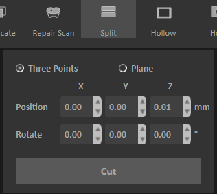
12.Split
The split tool that allows you to split a model along a single plane, reducing material from the base or cutting off unneeded parts of your model.
12.1.Three Points
Select the model, click the left mouse button three times on the model, there is a cutting surface. Left-click the selected point and drag to adjust the direction of the cutting surface. Click the "Cut" button selected model will besplit.
12.2.Plane
Method1: Adjust the position and rotate of the cutting plane in the toolbar. and then click the "Cut" button and the selected model will be split.
Method2: Adjust the rotate of the cutting plane in the toolbar. Move the mouse to adjust the position of the cutting plane and Click the left mouse button to confirm the split.
13.Hollow
The excessive waste of resin in printing solid model is avoided in this function, and the possibility of printing failure is avoided because of the weight.
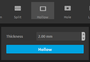
Operating Method: Adjust the wall thickness, and then click "Hollow" to carry out the internal hollowing operation of the selected model automatically. Use the "Slice Viewer" to view the internal hollowing condition.
Parameters:
Wall Thickness: refers to the thickness of the outer diameter minus the inner diameter of the model after the interior hollowing out
14.Hole
The Hole function is more likely to be used with the hollow function. The holes can let the air and excess resin out.
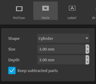
Operating Method: Select the shape of the hole, adjust the size and depth of the hole, and choose whether to "save hole". And then move the mouse and click on the target location of the model to make a hole.
Parameters:
- Shape: The shape of the hole.
- Size: diameter of the hole.
- Depth: The depth of the hole.
- Save hole: After the hole is punched, the hole part will be cut off to form a new model. If the box is selected, the hole model will be retained. If not, the hole model will be deleted by default.
15.Label
Here you can label your 3D models. This function is useful when you planning to print dozens of instances from the same 3D model but using different parameters or resins or any variate that could possibly causes differences on printing results. You can mark your 3D Models by adding labels on their surface, so you won't mixed up with printing results those are similar to each others.
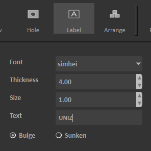
Operating Method: Choosing the font, thickness,size and bulge or sunken of the text,Enter the text to mark, Text follows movement when moving the mouse. And then click on the model to generate the label.
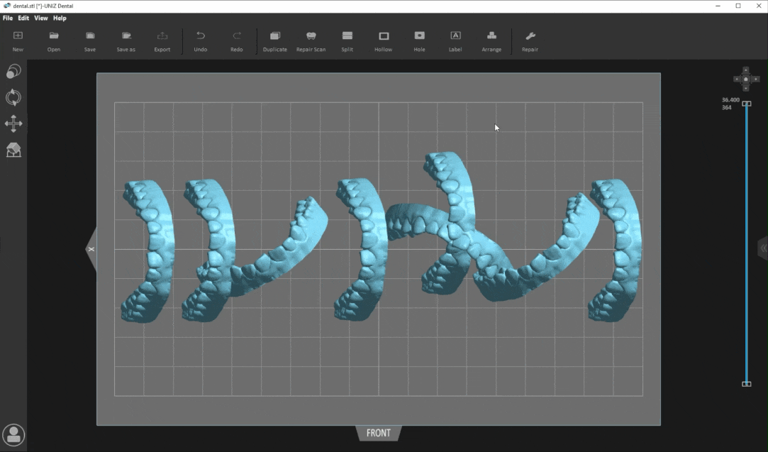
16.Arrange
Arrange function helps you realize the model layout quickly, improve work efficiency. Recommend and set the layout orientation for the selected 3D model before support.
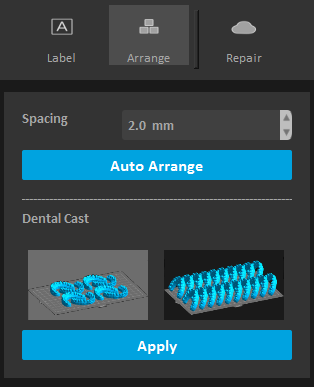
Method1: Adjust model spacing,and then Click "Auto Arrange" for automatic layout.
Method2: Select the vertical or horizontal direction for the “Dental model layout”, Click "Apply" and then vertical or horizontal layout of dental models will be quickly realized.
Note: Arrange will remove supports except horizontal layout.
17.Add support
The principle of 3D printing is to print layer by layer. If the part of the model is suspended, or the printed part couldn’t support the unprinted part, users need to add supports.
17.1.Support parameters
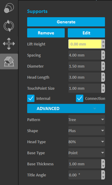
Lift height: If the model needs to be fully supported, the model lifting height needs to be set, the recommended value is 5mm; if the model only needs partial support, users needn’t to set the lift height;
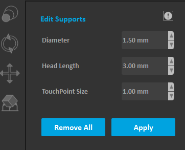
Set the Space, Diameter, Head Length, and Touch Point Size:
as shown below.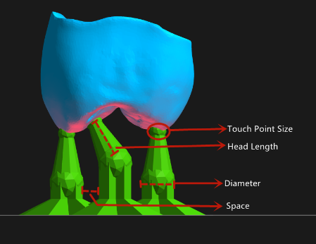
Internal support: If there is a suspension inside the model that needs to be added internal support, check this item;
Support connection: If the support is very long, and the stability of the support needs to be strengthened, check this item;
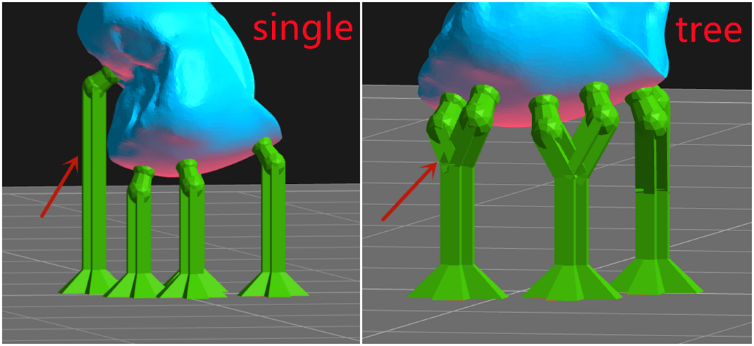
Pattern: tree structure and single structure.
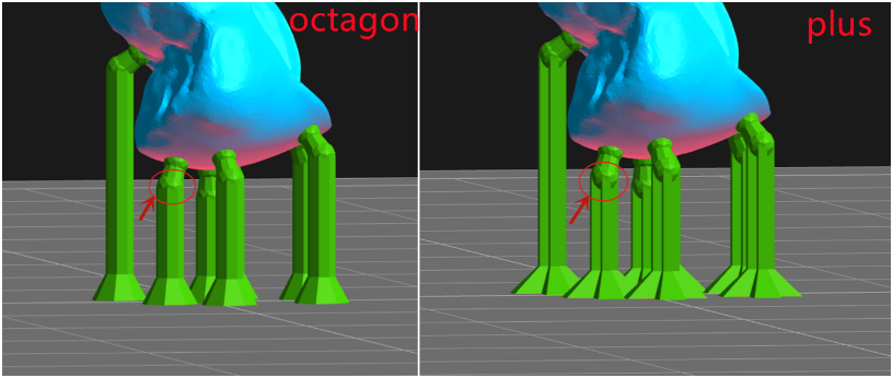
Shape:octagon structure and plus structure.
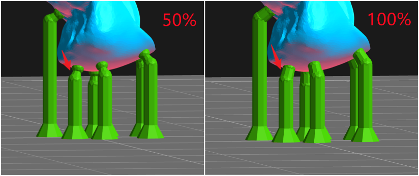
Head Type: The shape of the contact position between the support head and the model is a ball. The thickness of the connection between the support head and the ball differs with the setting of Head Type(50%~100%).
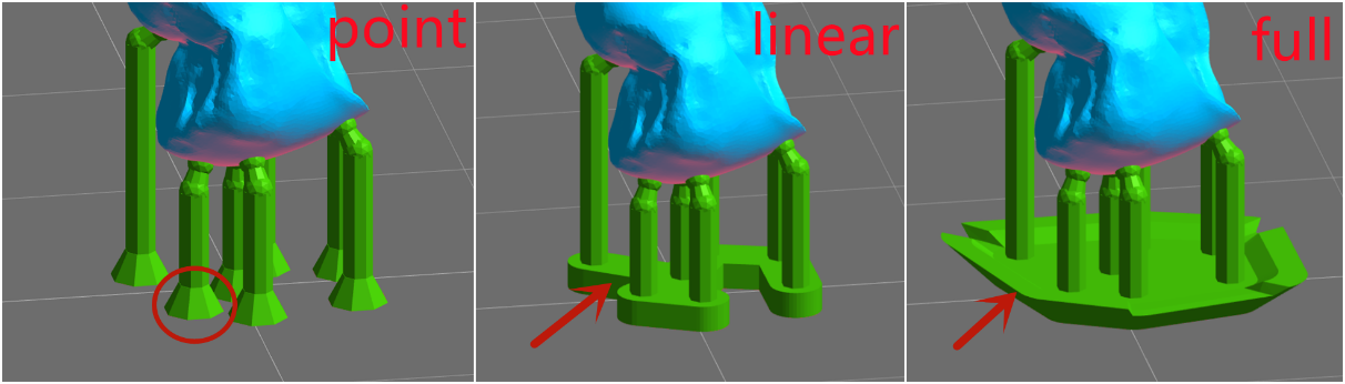
Base Type: The software offers four base types: Point, Line and Plane.
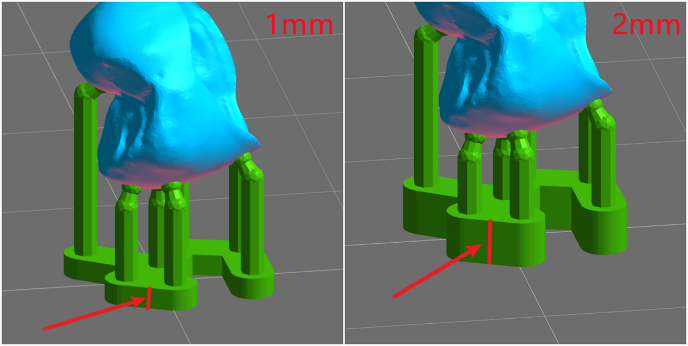
Base Thickness:The range of the base thickness is 0.5-2mm.
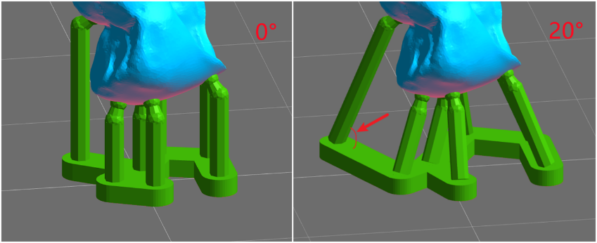
Tilt Angle: Set the Angle of support, The range is 0 to 20 degrees.
17.2.Auto-Add Supports
Operating Method: Select the model and adjust the appropriate parameters,and then click "Generate" to automatically generate support for the model. Click "Remove" to remove all the added support.
17.3.Editing supports
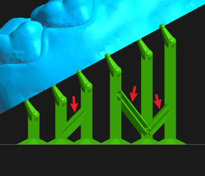
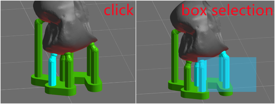
Operating Method: Select the model and click "Advanced" to adjust the appropriate parameters,and click the "Edit" button on the automatic support interface to enter the manual editing. In this mode, users can add, modify and delete supports. Move the mouse to the model, and if the green ball is marked at the mouse position, it means that the normal vector of the position is down and support can be added. Click the left mouse button to complete the new support work. If a red ball is marked at the mouse position, it means that the normal vector of the position is upward and no support is needed. Finally,click "Apply" to finish adding support manually.
Tip
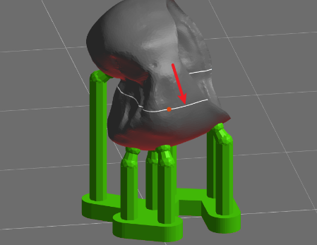
White contour lines:When you move the mouse, a white line will be displayed on the model. The white line is a contour line, which means all the points on the white line have the same z value. The white line can be used to easily find the floating point.
Select Supports:Mouse click and box selection are available to select the support.
Moving support head: Click on the support head and drag it to the target position on the model and then release. The position of the support head will be modified.
Moving support base:Left-click on the support base and drag it to the target position on the platform to release, the position of the support base will be modified.
Modifying Support Parameters: Select one or more supports, modify the support diameter, support head length and touch point size etc. the related properties of the model will be updated in real time.
Remove support:Press the "Delete" button to remove the selected support. Click “Remove All”, all the supports will be removed.
18.Slice
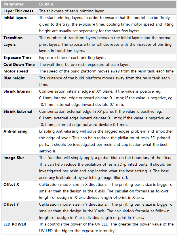
Slicing is the last and most important part of printing preprocessing. In the slice setting, you needs to select a profile which contains the printing parameters, including layer thickness, exposure time, cooling time, motor speed, rise height, etc. The printing parameters affect the success rate of printing.
18.1.Profiles Settings
18.1.1 Manufacturer settings
1.Select a printer type.
2.Select a printer.
3.Select a resin Manufacturer.
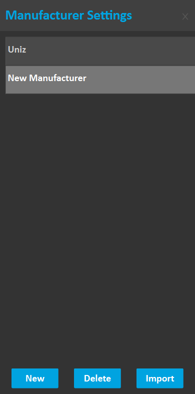
4.Click the button ... next to Manufacturer on the right toolbar to open the Manufacturer Settings box.
18.1.1.1 Add a manufacture
1.Open Manufacturer Settings box.
2.Click New.
3.Double click to edit name.
18.1.1.2 Modify a manufacturer name
1. Open Manufacturer Settings box.
2. Select a manufacturer.
3. Double click to edit name.
18.1.1.3 Delete a manufacturer
1. Open Manufacturer Settings box.
2. Select a manufacturer.
3. Click Delete.
18.1.1.4 Import a third-party manufacture’s profiles
1.Go to https://www.uniz.com/us_en/materials/open-material-library to download the up-to-date resin brand library,where you can check all the current Uniz-validated third party parameters. After selecting the target brand resin, click "Download Material Profiles" and save to local.
2.Open UNIZ Industry, open Manufacturer Settings box.
3.Click Import. A open box opens.
4.Select a config file (.zcfg) from the local file, and click OK to open it.
18.1.2 Profiles setting
1.Select a printer type
2.Select a printer
3.Select a resin manufacture
4.Click the button ... next to Profile on the right toolbar to open the Profiles Settings box.
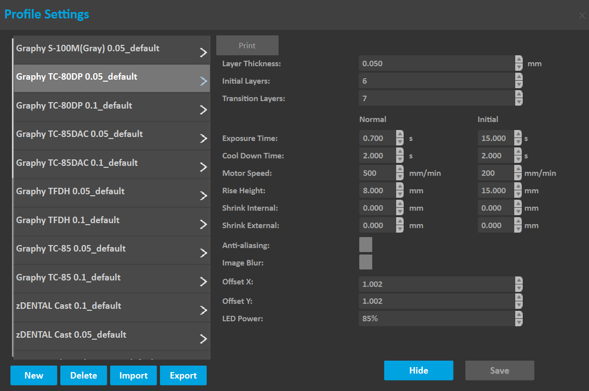
Parameters
18.1.2.1.Add Profile
Click the button"..." next to Profile on the right Tools to open the Profiles Settings box, click "New" button to get a set of parameters on the right, adjust parameter values according to requirements, click "Save" button to add successfully.
18.1.2.2.Modify Profile
Select a profile on the left List, modify the corresponding value on the right view, and click Save.
Note:The default parameters cannot be modified.
18.1.2.3.Delete Profile
Select a profile on the left List, click Delete, and confirm as prompted.
Note:The default parameters cannot be deleted.
18.1.2.4.Import Profile
Click "Import" button on the Profiles Settings box, select a profile file(.zcfg) from the local file, and click “ok” to open it.
18.1.2.5.Export Profile
Select the parameters to be exported on the configuration page, click Export, and save the parameters to the local PC as prompted.
18.2.Slice Models
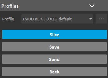
Select a profile in profile list, click the "Slice" button, all loaded models will be sliced using the parameters in the selected profile.
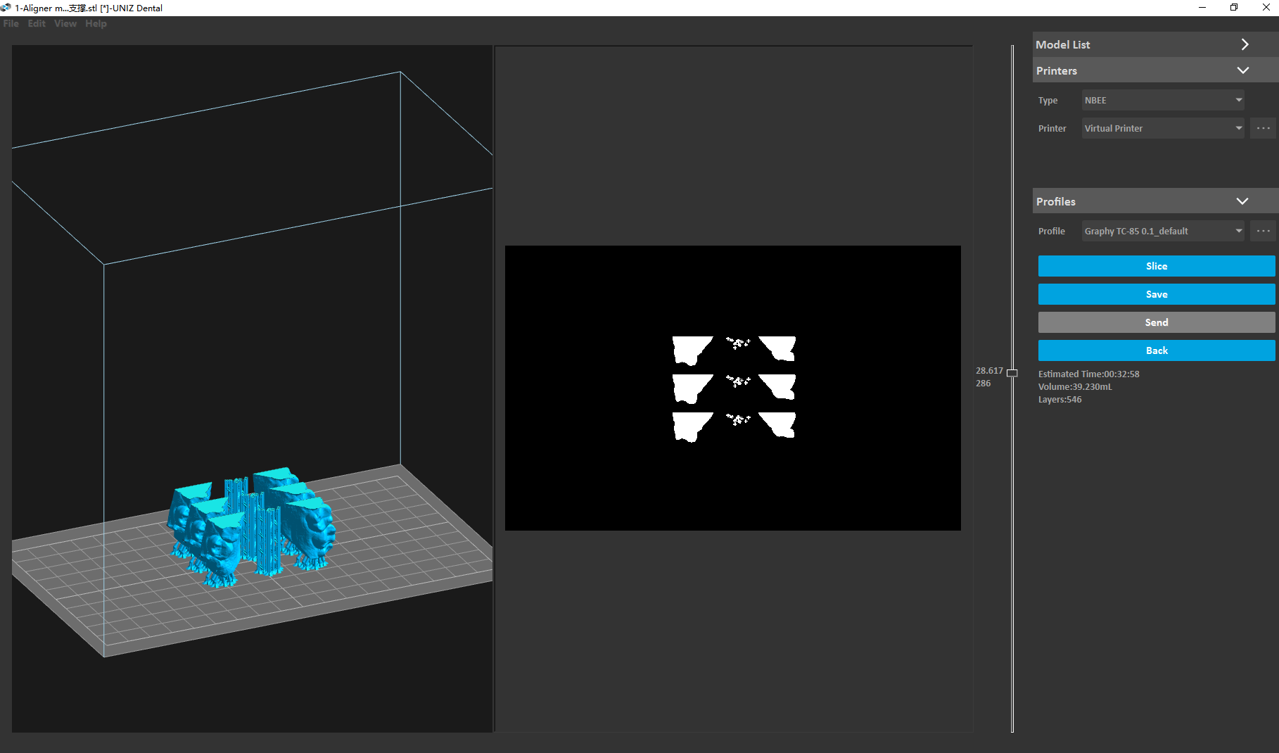
18.3.Slice Viewer
After the slicing is completed, the software will automatically switch to the slice preview window. Drag the sliding block up and down, and the left 3D window and 2D window will simultaneously display the slice at the height of the sliding block.
18.4.Save Slice
Click the "Save" button on the right side of the slice preview view to pop up the save path dialog box, click the "OK" button to start saving the slice to local disk.
18.5.Upload Slice
Click the "Send" button on the right side of the slice view to the selected printer in the same LAN. If the current slice is not saved, it will be saved to the local disk before sending.
- Step 2:Select a printer under the corresponding type. If you do not select, the printer type used last time will be recorded by default (when the software is opened for the first time, the default value of printer type will be displayed).
- Step 3:load the 3D model.
- Step 4:Use the appropriate tool to edit the model.
- Step 5:Set the printing parameters then slice.
- Step 6:Send the slice files to the printer through the U disk or use the network sending function, then start the print;


4.Printer Settings
This function mainly manages the printer type and printer list under the currently selected printer type. The printer list includes a virtual printer and real printers. Here is mainly to manage real printers, including automatically searching for printers in the LAN, manually adding printers in the LAN, deleting printers, and managing printer history slices.
4.1.Select Printer Type
Select a printer type, the software will automatically select the printer that have been added of that type.
4.2.Select Printer
Select a printer in Printer List. If there is no printer currently available, you can choose a Virtual Printer in the list. Virtual Printer is included in the printer list of each printer type. If you do not need to transfer slices based on LAN, select a virtual printer and then perform printing data preparation.
4.3.Add printer
Preconditions:
1)Turn on your printer and make sure it is connected to the network via Ethernet or Wi-Fi.
2)Ensure the printer is connected to the same network as the PC.
If you need to transfer slices to the printer based on LAN, you need to add the printer to the printer list. The software provides two methods: Auto Search and Add Manually.
4.4.Auto Search
1)Click the Button "..." after the Printer List Combox on the right Tools to open the printer settings box.
2) Click the "Refresh" button to automatically search for connected printers and add them to the list.
Note: Due to the network environment, there is a probability that the printer cannot be searched. In this case, it is recommended to add the printer manually.
4.5.Add Manually
1)You need to obtain the printer's IP address on the printer's touch screen.
2)Open the printer settings dialog box, click the "New" button, enter the IP address, and click the "Add" button.
3)If the printer is successfully detected, it will be added to Printer list. If you cannot connect to the target printer, please check the network settings.
Note: A new printer cannot be created when the software is in search.
4.6.Delete printer
Historical printer information is stored in the printer list. If there is an invalid printer in the list, you can delete it in the printer management; open the printer settings dialog box, select the printer, click the delete button, and confirm as prompted.
4.7.Manage printer's history slices
Show Slice List: In the printer settings box, select a printer and click the "Refresh Slices" button. The historical slices stored on the selected printer will be listed.
Delete Slice: Select a slice and click "Delete slice" to delete the selected slice.
5.Model management
To open 3D model or slices. UNIZ Industry supported file formats are: stl, obj, 3mf, amf, zprj, slc, zslr.
5.1.Open the model
- Method1:Hold down the left mouse button and drag one or more models into the Dental software icon on your desktop.
- Method2:Hold down the left mouse button and drag one or more models into the "3D Interactive window", and then Release the mouse and wait for the model to load to the view interface.
- Method3:Click the open button in Top toolbar1, and then select the model you want to load when the dialog box opens, finally, click "OK" and wait for the model to load into the "3D Interactive Window".
- Method4:In the menu bar, click "File" and the menu will pop up Then click "Open", and then select the model you want to load when the dialog box opens, finally, click "OK" and wait for the model to be loaded into the "3D Interactive Window".
5.2.Remove the model
- Method1:Click the right mouse button on the selected model to display the shortcut menu bar, and then selected model is deleted after clicking "Delete".
- Method2: Click "Model List" in the Right Toolbar to check all model names, After selecting the model, click the right mouse button to display the shortcut menu bar and then click Delete.
- Method3:Select the model or its name that you want to delete and then press the “delete” key on the keyboard.
5.3.Save the model
- Method1:In the menu bar, click "File" and the menu will pop up, and then click "Save" or" Save as "or" Export STL" , and then Save File window is displayed. Select a location to save the file.
- Method2:In the Top toolbar1,Click "Save" or " Save as " or " Export STL", and then Save File window is displayed and then Select a location to save the file.
6.Modify size
- Method1:Once the Size tab is open, the activated object can be scaled freely by holding the left mouse button on the object and moving the mouse.
- Method2: The activated object can also be scaled by inputting X/Y/Z values in the field. Press Enter to apply changes. Users can also click the up and down button to change the size. The object will scale uniform in Uniform Scaling mode.
- Method3:Modified scale,If a single model is selected, the model will be scaled according to the modified scale; if multiple models are selected, the scale of all models will be set to 1, and the modified scale will be scaled relative to 1.
- Method4:Units,toggle between millimeters and inches.
- Notes:Changing an object's size will break previously generated supports and you will need to redo these.
7.Moving model
7.1.Change Orientation
Models need to be adjusted the angle according to its characteristics to obtain better printing results.
- Method1:Change the values of x, y, and z angles on the Rotation tool dialog, the selected model Angle will be changed.
- Method2:Select the model, the manipulators will be suspended on the model, and then hover the mouse over the single ring of the selected model, finally, Long press the mouse and drag the ring to rotate the model along the axis of the ring.
- Method3: Press the " Align bottom Plane" button in the toolbar, and then Click on the target bottom plane of the model with the mouse and rotate the model quickly.
Notes:
Rotating a model along the X- or Y-axis supports will be removed.
Rotating a model along the Z-axis supports will not be removed.
7.2.Change Position
- Method1:The selected model is moved by changing the X/Y/Z values on the Position tool dialog. Click the "To Platform" button to modify the Z value of the selected model to zero, and the model will contact with platform. Click the "Center" button to move the selected model to the center of the XY plane.
- Method2:Manipulators will be suspended on the model, and then click and press selected model,,drag to the target location to release.
- Method3: Click the right mouse button on the selected model to display the shortcut menu bar. Click the "To Platform" button to modify the Z value of the selected model to zero, and the model will contact with platform. Click the "Center" button to move the selected model to the center of the XY plane.
- Method4: Click "Model List" in the Right Toolbar to see all model names, After selecting the model, click the right mouse button to display the shortcut menu bar. Click the "To Platform" button to modify the Z value of the selected model to zero, and the model will contact with platform. Click the "Center" button to move the selected model to the center of the XY plane.
Notes:
If the model has supports, modify the Z value and the supports will be removed.
8.Switch View
8.1.Facade
Changing the Angle of the model makes it easier to rotate, place, and add support.
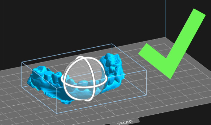
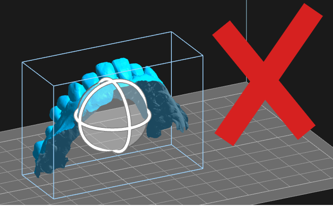
- Method1:Click the direction button in the view toolbar, the model will show its "Main View" or "Left view" or "right view" or "Top view" or "Front view".
- Method2:Press the right mouse button in the 3D window and drag it. If there is a selected model, the 3D scene will rotate around the center of the selected model. If no model is selected, it will rotate around the tray. If you press the Shift key while dragging the mouse, the view will pan with the drag of the mouse. Scroll the middle mouse button, and the 3D scene will zoom in and out.
- Method3:In the menu bar, click " View " and the menu will pop up, and then click the menu "Main View" / "Left View" / "Right View" / "Top View" / "Front View" to quickly switch the view.
- Method4:Slide the scroll wheel to zoom in or out of the view when the mouse is in the operating area.
8.2.Section view
When using the functions of hollowing, punching, adding support and slicing, check whether the interior of the model meets the printing standards.
Operating Method: Drag the upper slider to hide the upper part of the model and observe the section. Drag the lower slider to hide the lower part of the model and observe the section.
9.Repair
If the 3D model is damaged , the system will prompt user whether to repair,an exclamation point will appear in front of the item in Model List view. If the user chooses to ignore it, the model may fail to print. If the 3D model is defective, an exclamation point will appear in front of the item in Model List view.
Operating Method:
1)If there are some errors in the 3D model data, Click the "Repair Model" button, and the software will automatically repair the model. If the repair fails, a message indicating failure is displayed. If Only small holes is checked, the repair speed will be greatly improved when there are large holes that cannot be repaired.
2)The external surface of a normal model is bright blue, if the external surface of the model is dark blue, it means that the surface of the model is inverted, click " Invert " to repair the model.
10.Repair Scan
The repair scan tool allows for repairing the intraoral models. It exceeds the functionality of the basic repair tool by adding a basing function, making your model much easier to print and much more aesthetically pleasing.
10.1.Three Points
Adjust the base-height in "Repair Scan" box. Pick three points with the left mouse on the model surface to determine the cutting plane, the part that needs to be deleted will be marked in red by default. If the default selection is incorrect, please click the part to be deleted with left mouse. Click the "Repair" button selected model will automatically repair and complete the missing base..
10.2.Horizontal Plane
- Method1:Position the occlusal surface to face away from the build platform. Adjust the z value of the cut plane and base-height in the "Repair Scan" box. Click the "Repair" button selected model will automatically repair and complete the missing base.
- Method2:Position the occlusal surface to face away from the build platform. Adjust the base-height in "Repair Scan" box. Move the mouse to adjust the z value of the cut plane. Click the left mouse button to apply, the selected model will automatically repair and complete the missing base.
- Parameters:Z:It's the height of the z plane.
11.Duplicate
Method1: Adjusting the Number of copies on the duplicate tool dialog, Click the " Duplicate" button ad the selected model will be duplicated by the specified number.
Method2: Click the right mouse button on the selected model to display the shortcut menu bar. And then click the " Duplicate" button and the selected model will be duplicated by the specified number.
Method3:Click "Model List" in the Right Toolbar to check all model names. After selecting the model, click the right mouse button to display the shortcut menu bar. And then click the " Duplicate" button and the selected model will be duplicated.
12.Split
The split tool that allows you to split a model along a single plane, reducing material from the base or cutting off unneeded parts of your model.
12.1.Three Points
Select the model, click the left mouse button three times on the model, there is a cutting surface. Left-click the selected point and drag to adjust the direction of the cutting surface. Click the "Cut" button selected model will besplit.
12.2.Plane
Method1: Adjust the position and rotate of the cutting plane in the toolbar. and then click the "Cut" button and the selected model will be split.
Method2: Adjust the rotate of the cutting plane in the toolbar. Move the mouse to adjust the position of the cutting plane and Click the left mouse button to confirm the split.
13.Hollow
The excessive waste of resin in printing solid model is avoided in this function, and the possibility of printing failure is avoided because of the weight.
Operating Method: Adjust the wall thickness, and then click "Hollow" to carry out the internal hollowing operation of the selected model automatically. Use the "Slice Viewer" to view the internal hollowing condition.
Parameters:
Wall Thickness: refers to the thickness of the outer diameter minus the inner diameter of the model after the interior hollowing out
14.Hole
The Hole function is more likely to be used with the hollow function. The holes can let the air and excess resin out.
Operating Method: Select the shape of the hole, adjust the size and depth of the hole, and choose whether to "save hole". And then move the mouse and click on the target location of the model to make a hole.
Parameters:
- Shape: The shape of the hole.
- Size: diameter of the hole.
- Depth: The depth of the hole.
- Save hole: After the hole is punched, the hole part will be cut off to form a new model. If the box is selected, the hole model will be retained. If not, the hole model will be deleted by default.
15.Label
Here you can label your 3D models. This function is useful when you planning to print dozens of instances from the same 3D model but using different parameters or resins or any variate that could possibly causes differences on printing results. You can mark your 3D Models by adding labels on their surface, so you won't mixed up with printing results those are similar to each others.
Operating Method: Choosing the font, thickness,size and bulge or sunken of the text,Enter the text to mark, Text follows movement when moving the mouse. And then click on the model to generate the label.
16.Arrange
Arrange function helps you realize the model layout quickly, improve work efficiency. Recommend and set the layout orientation for the selected 3D model before support.
Method1: Adjust model spacing,and then Click "Auto Arrange" for automatic layout.
Method2: Select the vertical or horizontal direction for the “Dental model layout”, Click "Apply" and then vertical or horizontal layout of dental models will be quickly realized.
Note: Arrange will remove supports except horizontal layout.
17.Add support
The principle of 3D printing is to print layer by layer. If the part of the model is suspended, or the printed part couldn’t support the unprinted part, users need to add supports.
17.1.Support parameters
Lift height: If the model needs to be fully supported, the model lifting height needs to be set, the recommended value is 5mm; if the model only needs partial support, users needn’t to set the lift height;
Set the Space, Diameter, Head Length, and Touch Point Size:
as shown below.
Internal support: If there is a suspension inside the model that needs to be added internal support, check this item;
Support connection: If the support is very long, and the stability of the support needs to be strengthened, check this item;
Pattern: tree structure and single structure.
Shape:octagon structure and plus structure.
Head Type: The shape of the contact position between the support head and the model is a ball. The thickness of the connection between the support head and the ball differs with the setting of Head Type(50%~100%).
Base Type: The software offers four base types: Point, Line and Plane.
Base Thickness:The range of the base thickness is 0.5-2mm.
Tilt Angle: Set the Angle of support, The range is 0 to 20 degrees.
17.2.Auto-Add Supports
Operating Method: Select the model and adjust the appropriate parameters,and then click "Generate" to automatically generate support for the model. Click "Remove" to remove all the added support.
17.3.Editing supports
Operating Method: Select the model and click "Advanced" to adjust the appropriate parameters,and click the "Edit" button on the automatic support interface to enter the manual editing. In this mode, users can add, modify and delete supports. Move the mouse to the model, and if the green ball is marked at the mouse position, it means that the normal vector of the position is down and support can be added. Click the left mouse button to complete the new support work. If a red ball is marked at the mouse position, it means that the normal vector of the position is upward and no support is needed. Finally,click "Apply" to finish adding support manually.
Tip
White contour lines:When you move the mouse, a white line will be displayed on the model. The white line is a contour line, which means all the points on the white line have the same z value. The white line can be used to easily find the floating point.
Select Supports:Mouse click and box selection are available to select the support.
Moving support head: Click on the support head and drag it to the target position on the model and then release. The position of the support head will be modified.
Moving support base:Left-click on the support base and drag it to the target position on the platform to release, the position of the support base will be modified.
Modifying Support Parameters: Select one or more supports, modify the support diameter, support head length and touch point size etc. the related properties of the model will be updated in real time.
Remove support:Press the "Delete" button to remove the selected support. Click “Remove All”, all the supports will be removed.
18.Slice
Slicing is the last and most important part of printing preprocessing. In the slice setting, you needs to select a profile which contains the printing parameters, including layer thickness, exposure time, cooling time, motor speed, rise height, etc. The printing parameters affect the success rate of printing.
18.1.Profiles Settings
18.1.1 Manufacturer settings
1.Select a printer type.
2.Select a printer.
3.Select a resin Manufacturer.
4.Click the button ... next to Manufacturer on the right toolbar to open the Manufacturer Settings box.
18.1.1.1 Add a manufacture
1.Open Manufacturer Settings box.
2.Click New.
3.Double click to edit name.
18.1.1.2 Modify a manufacturer name
1. Open Manufacturer Settings box.
2. Select a manufacturer.
3. Double click to edit name.
18.1.1.3 Delete a manufacturer
1. Open Manufacturer Settings box.
2. Select a manufacturer.
3. Click Delete.
18.1.1.4 Import a third-party manufacture’s profiles
1.Go to https://www.uniz.com/us_en/materials/open-material-library to download the up-to-date resin brand library,where you can check all the current Uniz-validated third party parameters. After selecting the target brand resin, click "Download Material Profiles" and save to local.
2.Open UNIZ Industry, open Manufacturer Settings box.
3.Click Import. A open box opens.
4.Select a config file (.zcfg) from the local file, and click OK to open it.
18.1.2 Profiles setting
1.Select a printer type
2.Select a printer
3.Select a resin manufacture
4.Click the button ... next to Profile on the right toolbar to open the Profiles Settings box.
Parameters
18.1.2.1.Add Profile
Click the button"..." next to Profile on the right Tools to open the Profiles Settings box, click "New" button to get a set of parameters on the right, adjust parameter values according to requirements, click "Save" button to add successfully.
18.1.2.2.Modify Profile
Select a profile on the left List, modify the corresponding value on the right view, and click Save.
Note:The default parameters cannot be modified.
18.1.2.3.Delete Profile
Select a profile on the left List, click Delete, and confirm as prompted.
Note:The default parameters cannot be deleted.
18.1.2.4.Import Profile
Click "Import" button on the Profiles Settings box, select a profile file(.zcfg) from the local file, and click “ok” to open it.
18.1.2.5.Export Profile
Select the parameters to be exported on the configuration page, click Export, and save the parameters to the local PC as prompted.
18.2.Slice Models
Select a profile in profile list, click the "Slice" button, all loaded models will be sliced using the parameters in the selected profile.
18.3.Slice Viewer
After the slicing is completed, the software will automatically switch to the slice preview window. Drag the sliding block up and down, and the left 3D window and 2D window will simultaneously display the slice at the height of the sliding block.
18.4.Save Slice
Click the "Save" button on the right side of the slice preview view to pop up the save path dialog box, click the "OK" button to start saving the slice to local disk.
18.5.Upload Slice
Click the "Send" button on the right side of the slice view to the selected printer in the same LAN. If the current slice is not saved, it will be saved to the local disk before sending.