Set Up Your Print
Overview
Open Uniz Desktop and click Control Button to show the 3D model viewer.
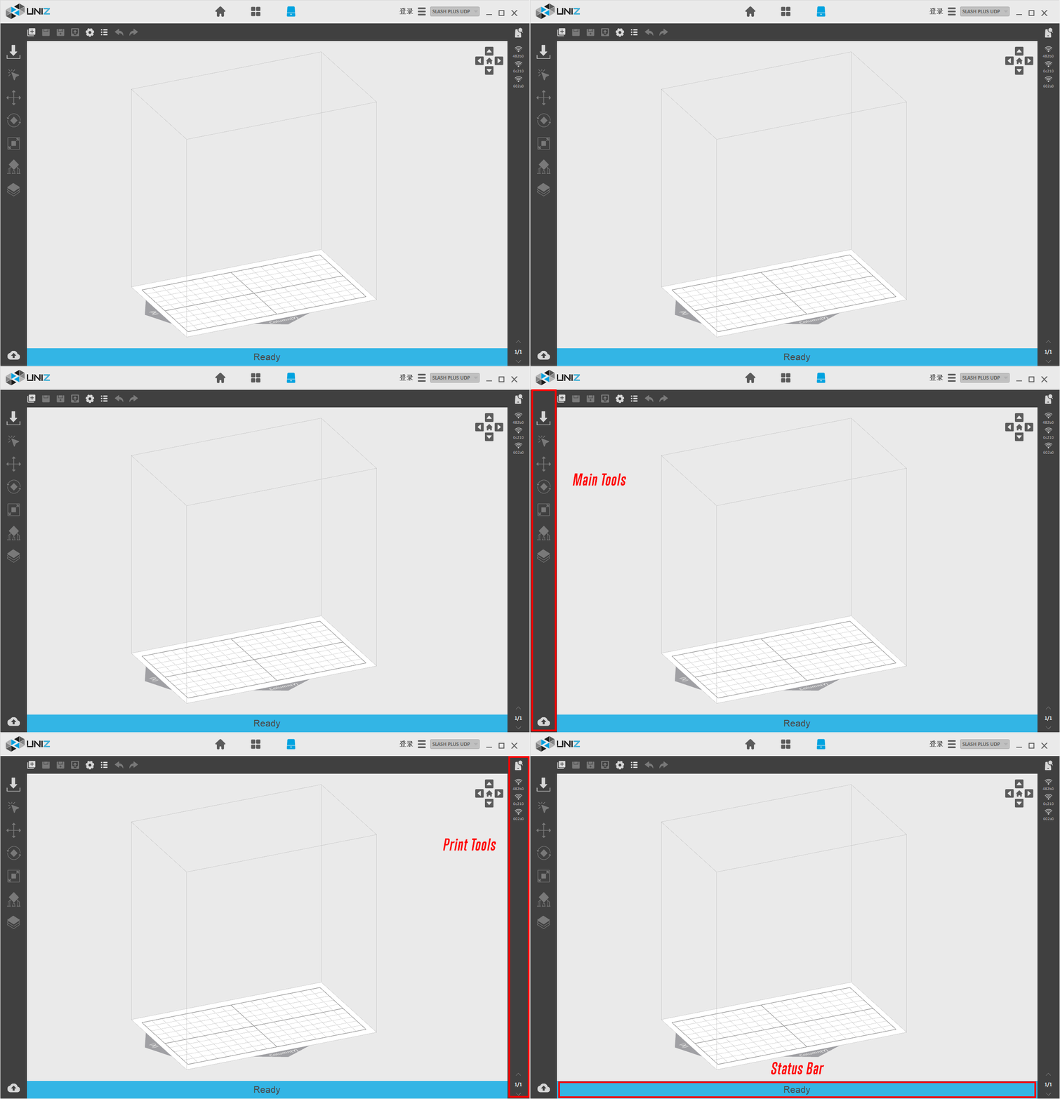
The main interface has five components:
-
1. 3D Viewer
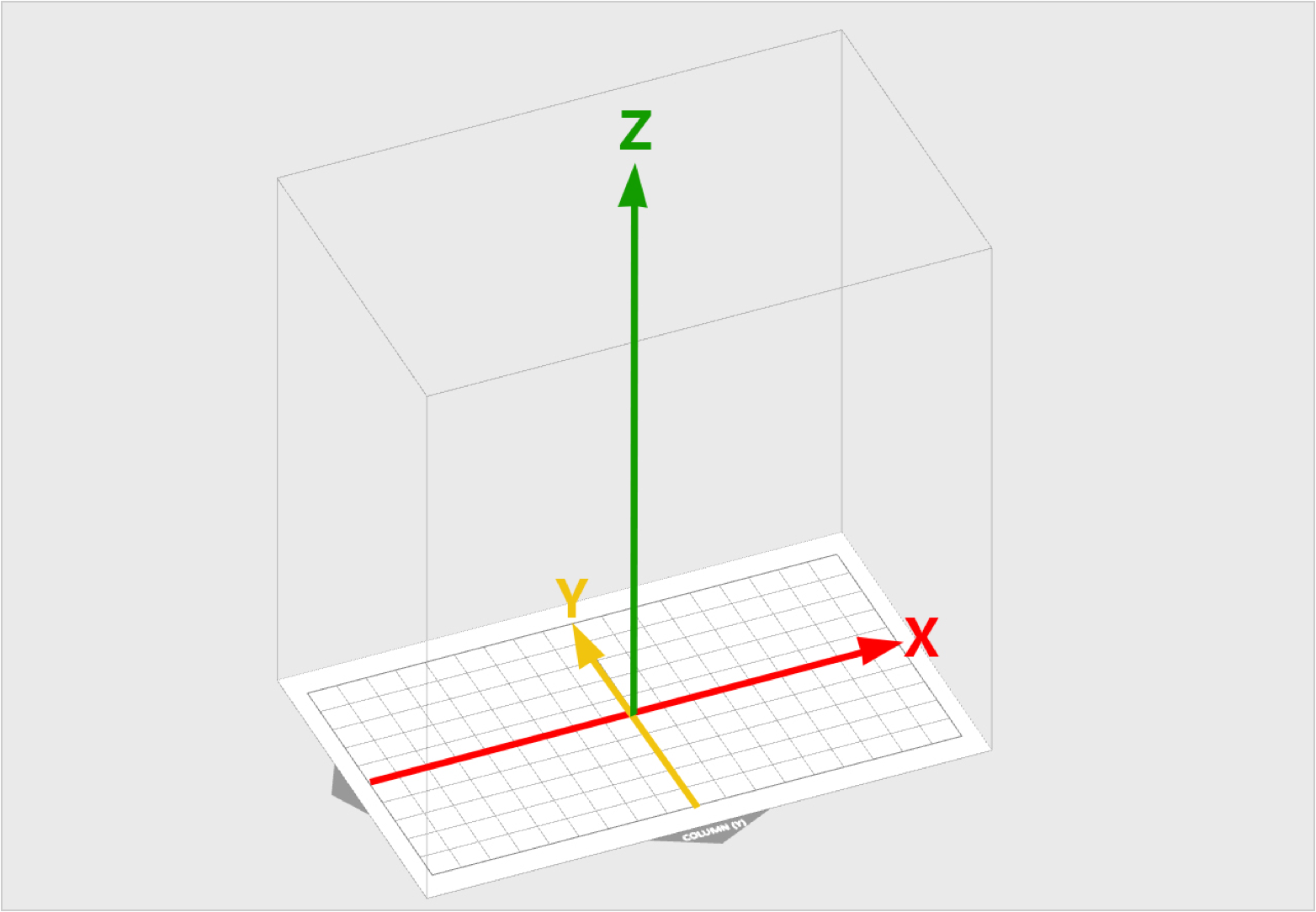
-
2. Main Tools







-
3. Additional Tools


-
4. Printer Control

Uniz provides printer control function based on USB and network connection. This function also supports multiple printers’ control. Printer connected via USB will be marked with the
 icon in the right printing tool bar.
Click the Search button in the tool bar to search all the printers (only selected printer type) in the same network of the computer which will be marked with the
  icon.
icon.
Printer connected via both USB and network will be marked with the icon and USB communication will be prior.
 TIP
1 Only printers that are identical to the pre-selected printer type upon software start-up will be shown in the right toolbar.
2 More reliable connection will be preferable to use when there are many ways applicable in the printer.
USB>Ethernet>Wi-Fi
-
5. Status bar

The status bar appears along the lower edge of the window and shows software progress, such as the loading, generating support, and slicing progresses.
Load 3D Model
To load one or more 3D models, you may either drag-and-drop into the 3D viewer, click Load File Button from the Main Tools, or double click on the file directly (if Uniz Desktop is set as default software to open such file format). File format supported: STL, OBJ, AMF, 3MF and UNIZ.
TIP
UNIZ file does not support multiple load in parallel.
Model selection and Manipulators
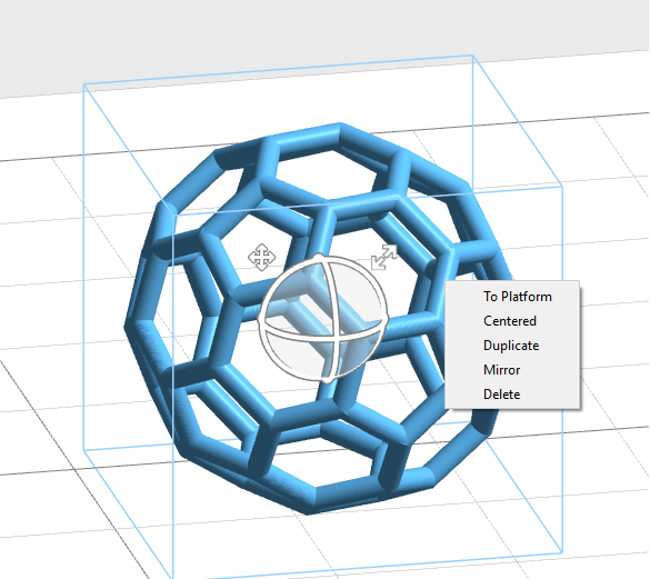
In the interface of Position, rotation, scale and automatic support, users can select the model by clicking with the left mouse or pulling the box with the left mouse button. The unselected model is gray and the selected model is blue.
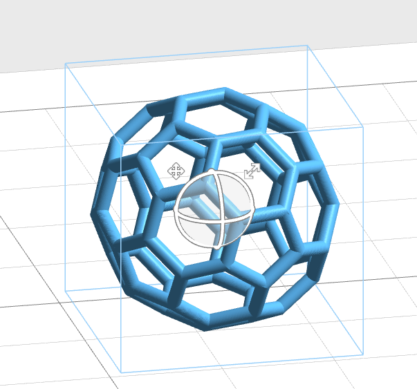
1. Select the model in the interface of position, rotation and scale. Manipulators will be suspended on the model.
- Position: click and press the position icon on the top left of the controller, drag to the target position to release.
- Rotation: click and press the circle on the controller to drag and release, the model will rotate around the corresponding axis.
- Scale: click and press the zoom icon on the top right of the controller to drag the zoom model.
2. In the interfaces of position, rotation and scale, right-click the selected model to pop up the menu, which specifically includes sub items such as “To Platform”, “Centered”, “Duplicate”, “Mirror” and “Delete”. Select sub items and perform relevant operations.
Change View
Viewing your model from preferred angle will benefit model positioning. To rotate the view, right click and drag around the activated object. To pan, hold the shift key and click-drag with right mouse or holding scroll wheel and move mouse around. To zoom in or out, use the scroll wheel.
Change Position
Pressing the Position Button ![]() will open following sub menu.
will open following sub menu.
Select the model, the manipulators will be suspended on the model. Click and press the position icon on the top left of the manipulators, drag to the target location to release.
Once the Position tab is open, hold the left mouse button on the object and move the mouse to move the object freely in the X-Y plane. If the Shift key is held down, the object will be moved up and down along the Z-axis instead.
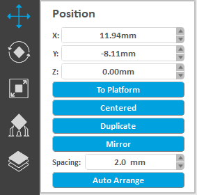
- The activated object can also be moved by inputting X/Y/Z values in the field, press Enter to apply changes.
- Bring active part in contact with platform.
- Center active part on platform.
- Duplicate active part.
- Users can modify the distance between models when placing multiple models automatically in the spacing input box.
- Click on the "Auto Arrange" button to rearrange the model according to the spacing and move it to the center of the build platform. Multiple clicks on the "automatic placement" button will result in different placement strategies for the model.
TIP
- Make sure the models are distributed evenly on build platform.
- Un-balanced forces on the build platform may result in inferior precision or cracking.
Change Orientation
Click the rotation button ![]() in the left sidebar to enter the rotation interface.
in the left sidebar to enter the rotation interface.
Select the model, the manipulators will be suspended on the model. Click and press the ring on the controller to drag and release, the model will rotate around the corresponding axis.
Press the left mouse button on the selected model to drag, and the model will rotate freely.
Notes:
Rotating a model along the X- or Y-axis removes supports.
Rotating a model along the Z-axis does not change supports.
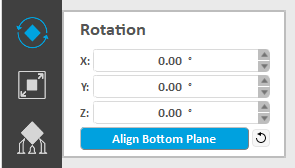
- The activated object can also be rotated by inputting X/Y/Z values in the field. Press Enter to apply changes. Uniz's orientation tools are relative, not absolute ,so the X, Y, and Z rotation angles reset to 0 degrees after applying a rotation.
- Press "To Align Bottom Plane" button to align the selected plane to the bottom of build platform.
- Click the Reset Button
 to restore the activated object to the original status.
TIP
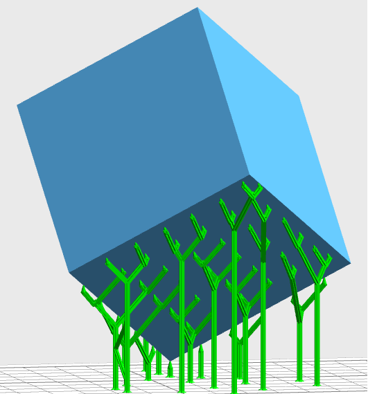
Large Flat surfaces or Long Straight line with supports may be printed at oblique angle of at least 10º to the build platform for higher success rate. The forces during peeling may distort the extremely thin layer of a flat surface or a line mounted on the support structures if printed horizontally. If a planar surface or thin line is oriented at an oblique angle, there is only little overhang for each new layer. Furthermore, thin-walled parts occupy significant less area in a slice when printed at an oblique angle.
Recommended
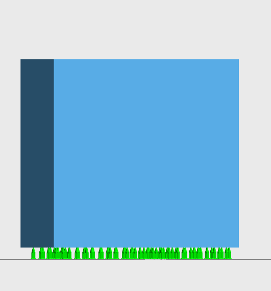
Not Recommended
Modify Size
Press the Size Button ![]() on the main tools will open following sub menu.
on the main tools will open following sub menu.
Select the model, the manipulators will be suspended on the model, click and press the zoom icon on the top right of the controller, and drag the zoom model.
Once the Size tab is open, the activated object can be scaled freely by holding the left mouse button on the object and moving the mouse.

- The activated object can also be scaled by inputting X/Y/Z values in the field. Press Enter to apply changes. The object will scale uniform in Uniform Scaling mode. And in Non-uniform Scaling mode it will scale for each axis without affecting the other axes.
- If you prefer to scale to a fixed ratio put value in the Scale.
- Click the Reset Button
 to restore the activated object to the original size.
 - Units: toggle between millimeters and inches.
TIP
Changing an object’s size will break previously generated supports and you will need to redo these. Note that change size by modifying scale value does not support multi-select.
Generate Supports
To meet requirements of models in different sizes and structural patterns, the software provides multiple support parameter options. Adjusting support parameters may lead to better printing results or printing failure which depends on the user's printing knowledge.
There are two ways for generating supports: Automatic Generation and Manual Edit.
Automatic Generation
Set support spacing, support diameter and other parameters based on the size and structure of the model.
Eventually, clicking the Generate button to generate supports automatically.
Manual Edit
Add one support, Edit one support or delete supports.
To complete edit function and switch to automatic mode by clicking Apply button.
TIP
The Generate button are only enable when a model is being selected and activated.
For more details, see: Generate Support
Slice
Press the Slice Button ![]() on the main tools will open two sub menus, the left menu is to start Slice and Show Slices, and the right drag bar and menu is for customization of slice profile.
on the main tools will open two sub menus, the left menu is to start Slice and Show Slices, and the right drag bar and menu is for customization of slice profile.
-
Click Slice Button to slice all models on the build platform with the defined parameters. The estimated print information will show in the status bar.

Click Show Slices Button to check slice of any sliced layer.
For more details, see: Slice
Printer connected via USB will be marked with the  icon in the right printing tool bar.
Click the  button in the tool bar to search all the printers in the same network which will be marked with the
  icon.
icon.
Press the printer icon  or
or  , to open the Printer Control Panel. The Printer Control Panel is used to control the printer for printing and regular maintenance. For more details, see: Print Tools
-
Print Process
-
1. Send to Printer
Click Start Button
 to send current slice to this printer.
 -
2. Complete the File Transfer
Once you click Start, Uniz Desktop's progress bar and the printer's front LED circle button will indicate the file transfer progress.
-
3. Confirm Print Job
Make sure that your printer is ready to print and then touch the printer's front LED circle button to confirm print job.
-
WARNING
Before final confirmation, please make sure the build platform, resin tank, and resin bottle are installed. Make sure the build platform and resin tank are clear of debris. Make sure the resin level sensor is properly installed.
After confirmation, you may disconnect your computer from the printer.
DO NOT disconnect the printer and the software or turn off the Uniz software during the data transmission.
Upload Slice(Optional)
If you want to share your print in Uniz Cloud, press the Upload Button  on the main tools to open following sub menu.
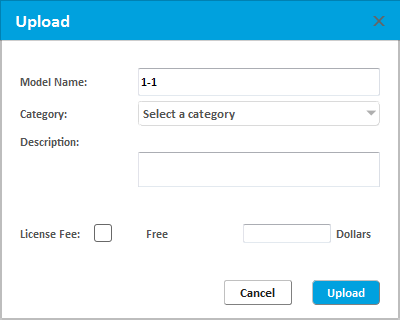
Images must contain photos of your print.
After your upload completed we will look through your request, if pass audits we will mail you and your slice will be upload to Uniz cloud.
In This Article
- Overview

- Load 3D Model

- Model selection and Manipulators

- Change View

- Change Position

- Change Orientation

- Modify Size

- Generate Supports

- Slice

- Print

- Upload Slice

The Previous Articles
- Design Specification
- Installation & Setup
- Printer Network
- Activate the Printer
- Trial and Trial Expiration
- Upgrade the Printer License
- Upgrade the Printer Firmware
- Remote Monitoring
- Accessory replacing remind and timer reset
- Store
- library
- Set Up Your Print
- One Click Print
- Generate Support
- Slice
- Print Tools
- Edit 3rd Resin
- Edit Preference
- Additional Tools

