Generate Supports
To meet requirements of models in different sizes and structural patterns, the software provides multiple support parameter options. Adjusting support parameters may lead to better printing results or printing failure which depends on the user's printing knowledge.
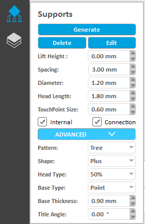
There are two ways for generating supports: Automatic Generation and Manual Edit Click the Supports button on left to open the settings dialogue box:
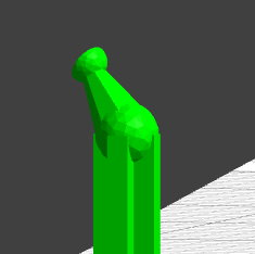
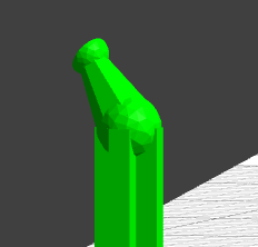
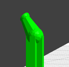
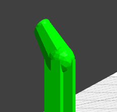
Supports Structure
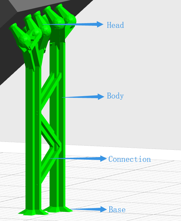
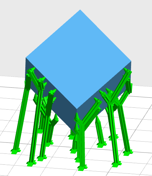
Support consists of four main parts: base, body, connections and head. The wide flat base ensures it sticks to the platform. The connections are used to reinforce multiple long supports. The support head is perpendicular to the model surface, preventing the support from sticking to the model and facilitating the removal of the support.
Support Parameters
Lift Height
Setting up the height of the selected model from the build platform surface. Modifying this parameter will delete the existing supports on the model.
Spacing
Spacing sets the horizontal distance between supports automatically to control the supports density.
Diameter
Diameter setting controls the thickness of support.
Head Type
The shape of the contact position between the support head and the model is a ball. The thickness of the connection between the support head and the ball differs with the setting of Head Type.
Head Length
The model size, the hollow part volume and the support thickness determine that head length should be set differently to avoid the support and model sticking.
Touch point Size
The touch point size between the support and the model needs to be weighed when setting up
- Small touch points are easier to remove, but printing may fail due to the overweight of the model.
- Big touch points increase the reliability of the supports but may overlap the details of the model surface and cause problems with removal, or may result in the loss of the model surface quality.
Pattern
Support structure includes tree and simple type
Tree Type
Simple Type
Shape
Support shape includes cross and octagon shape
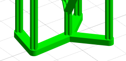
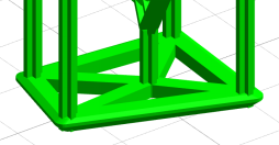
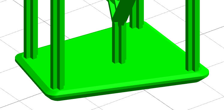
Base Type
The software offers four base types: Point, Line, Triangulation and Plane.
Base Thickness
Base thickness is set here.
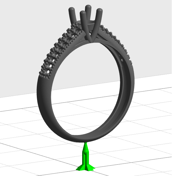
Internal Supports
Tick the Internal Support box and support will be created in the overhung part of the model to ensure it can be successfully printed when using automatic support generation. The lack of internal support can cause printing failure of the dangling part. The left picture below is with internal supports and the right one is without. This option is ticked by default.
Internal Supports
Non Internal Supports
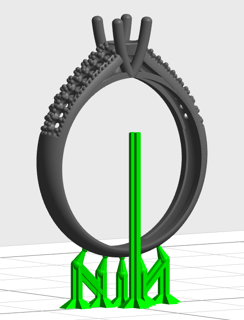
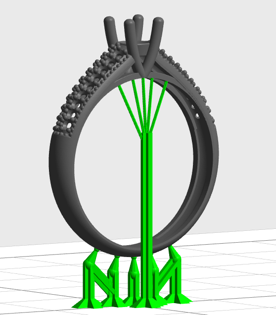
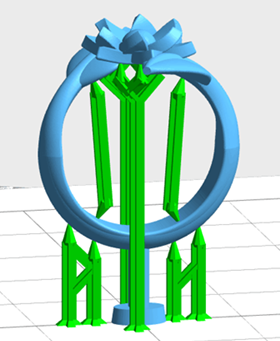
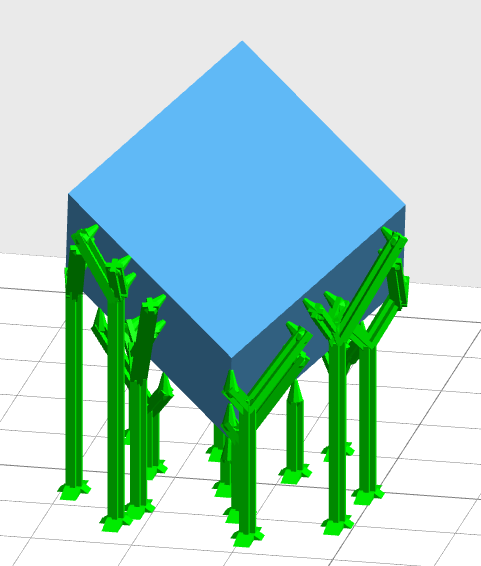
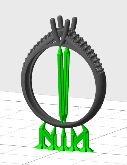
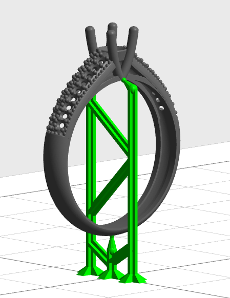
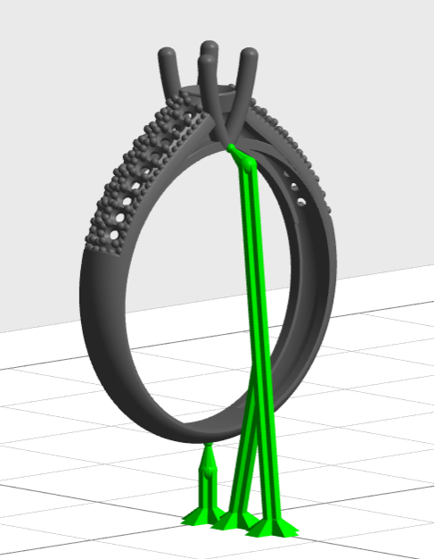
Connection
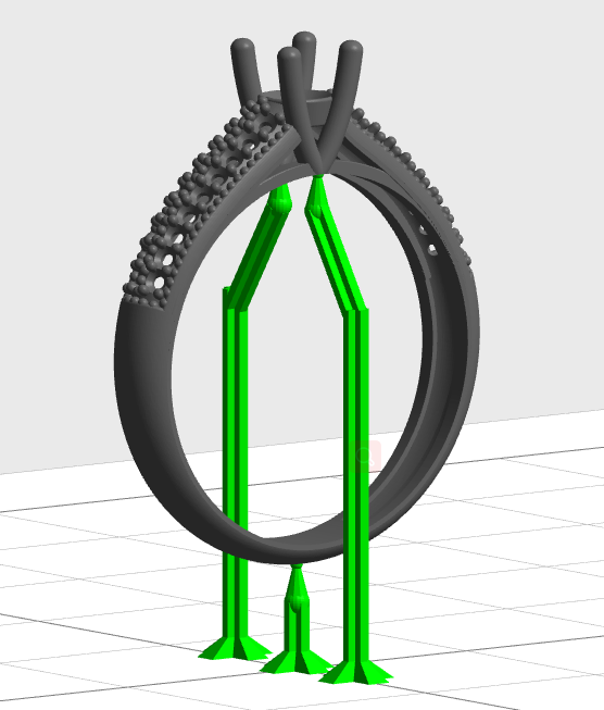
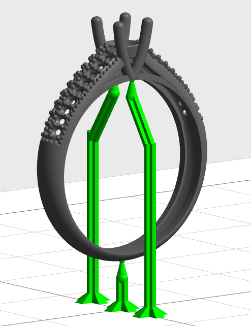
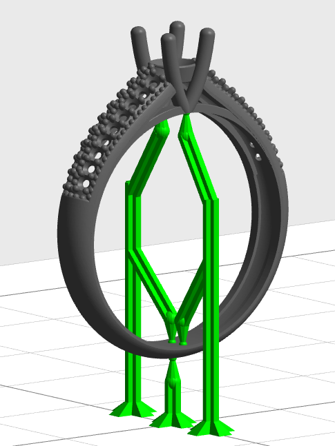
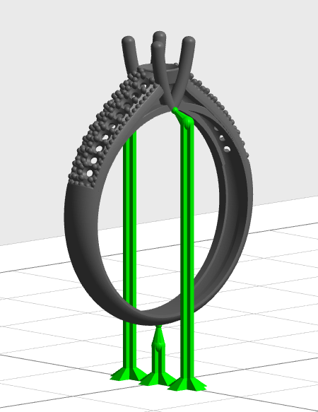
Long supports are unstable in structure. Ticking the Connection box will add connections between long supports which reinforce their stabilities. The left picture below is with connections and the right one is without. This option is ticked by default.
Support Angle
Supports will be generated where the angle of the model part surface and the horizontal direction is smaller than the Support Angle, otherwise they will not be generated. Bigger Support Angle will create supports for wider scope of model part. Set this value to prevent generating supports at steep places and to eliminate unnecessary supports. Users can manually set the angle ranging from 45°to 75°, and the default angle is 60°.
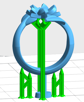
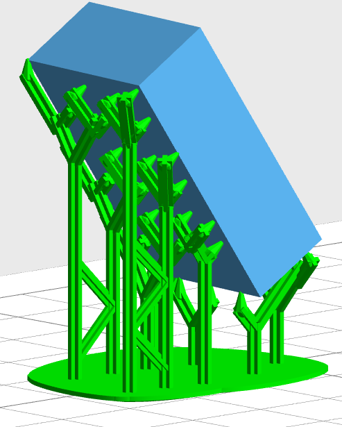
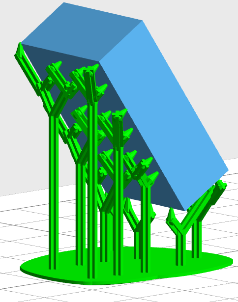
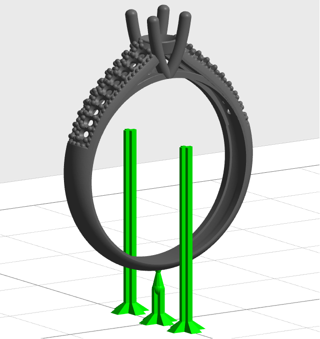
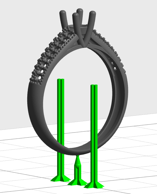
Tilt Angle
To ensure discontinuous exposure in part area under UDP mode, supports need to be tilted. Users can manually set the tilt angle ranging from 0°to 20°, and the default angle is 0°. The left picture below is with vertical supports and the right one is with tilted supports.
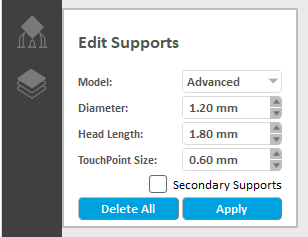
Manual Edit
Supports interface will be switched to manual edit mode by clicking Edit button.
Manual edit includes two modes: normal mode and advanced mode. The normal mode operation is the same as the manual edit in version 1.6, and the advanced mode is new in version 2.0. The biggest difference between the two modes is setting up new support.
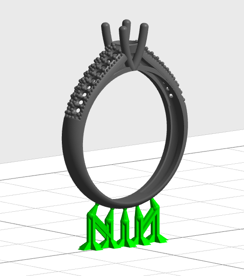
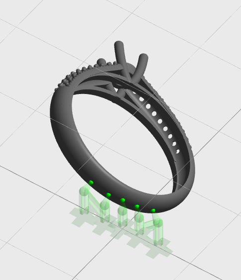
In the manual support mode, the support display will be different at different viewing angles. The supports will be fully displayed when looking at eye level and looking down. However, the support body and support base will become transparent when looking up.
To complete edit function and switch to automatic mode by clicking Apply button.
TIP
The Generate button are only enable when a model is being selected and activated.
1. Normal mode
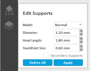
The normal mode interface:
In the normal mode, you can add support, delete selected support, modify selected parameters (diameter, head length of support and the size of touch point), and modify the support head or the position of support base for selected support.
1) Select support
Mouse click and box selection are available to select the support. The selected support will be highlighted.
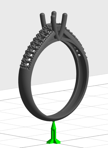
2) Add support
A line perpendicular to the surface of the model will be displayed when you move the mouse pointer on the model. If the line shows in green, it means that you can add support here. If it is red, it means that the position is not suitable for adding support. Clicking the left mouse button will add a new support perpendicular to the build platform at the mouse pointer position.
3) Delete support
Press the "Delete" button to remove the selected support.
4) Edit selected support parameters
Select one or more supports, modify the support diameter, support head length and touch point size etc. the related properties of the model will be updated in real time.
5) Edit the position of selected support
Click on the support head and drag it to the target position on the model and then release. The position of the support head will be modified.
Simple support (non-tree mode support) in contact with the build platform, press the Shift key and left-click on the support head, and drag it to the target position on the model to release it. The support body is kept perpendicular to the build platform, and the support base move at the same time.
Left-click on the support base and drag it to the target position on the platform to release, the position of the support base will be modified.
Drag the support head of the internal support onto the platform to change the internal support to a non-internal support.
Drag the non-internal support to the model to change the non-internal support to an internal support.
Note:
If the model turns red when you drag it, which indicates that the support is improper at this position. The support will be deleted if you release the mouse after dragging the internal support or support base to the mid-air.
2. Advanced mode
The interface of advanced mode is as follows:
In advanced mode, you can add new support, delete selected support, modify selected parameters (diameter, length of support head, and touch point size), and modify the position of selected support. The difference from the normal mode is as follows: The mouse operation of adding new support in the advanced mode is press-> drag
Except for the connected supports from the model to the platform, the connected supports from model to support, support to model, support to support, support to platform, and vertical support on the platform, tiny support, etc are also can be generated in the Advanced Mode.
The way to modify the supports is same as in the Normal Mode.
A line perpendicular to the model surface will displayed when move the mouse over the model. A green line means supports can be added here. A red line means this position is not suitable for adding support.
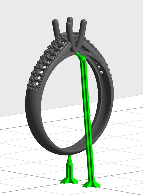
1) Build the connected support from model to platform
When in an overlooking angle, press the left mouse button on the model, dragge it to the platform( the support will be changed from internal support head to support foot) , and release the mouse to generate a new support.
PS: This operation won't work when the support is transparent( in looking up angle)
2) Build the internal support
Press the mouse on the model, and then drag ( the internal support head appears) and release the mouse to generate a new internal support.
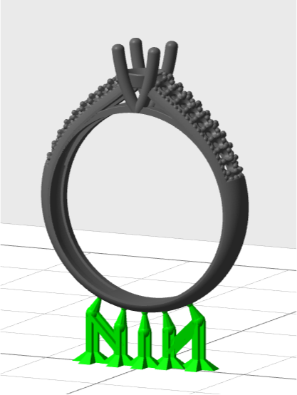
3) Build the vertical support on the platform
When in an overlooking angle, hold down the Alt key, click the mouse on the platform, and then drag and release the mouse to generate a vertical support.
PS: This operation won't work when the support is transparent( in looking up angle)
4) Build the connected support from model to support
Press the mouse on the model, drag it to the support (the internal support head or support foot disappears), and then release the mouse to generate the connected support from model to support.
5) Build the connected support from support to model
When in an overlooking angle, press the mouse on the support, drag it to the model (the internal support head appears), and then release the mouse to generate the connected support from support to model.
PS: This operation won't work when the support is transparent( in looking up angle)
6) Build the connected support from support to support
When in an overlooking angle, press the mouse on the support, and drag it to the support (the internal support head or support foot disappears). Release the mouse to generate the connected support from support to support
PS: This operation won’t work when the support is transparent( in looking up angle)
7) Build the connected support from support to the platform
When in an overlooking angle, press the mouse on the support, drag it to the platform (the shape becomes a support foot), release the mouse to generate the connected support from support to the platform
PS: This operation won’t work when the support is transparent( in looking up angle)

Build the tiny support
Check the tiny support option to build the internal support, and the connected support from support to support, support to model, model to support