Using UNIZ Maker
This article applies to IBEE
Ⅰ. Brief Introduction
UNIZ Maker is a slicing software designed especially for IBEE, the newest 3D printer of UNIZ. The software provides many functions including loading, typesetting, rotation and scaling models, generating supports, slicing and exporting slices. The following picture shows the interface of the software.
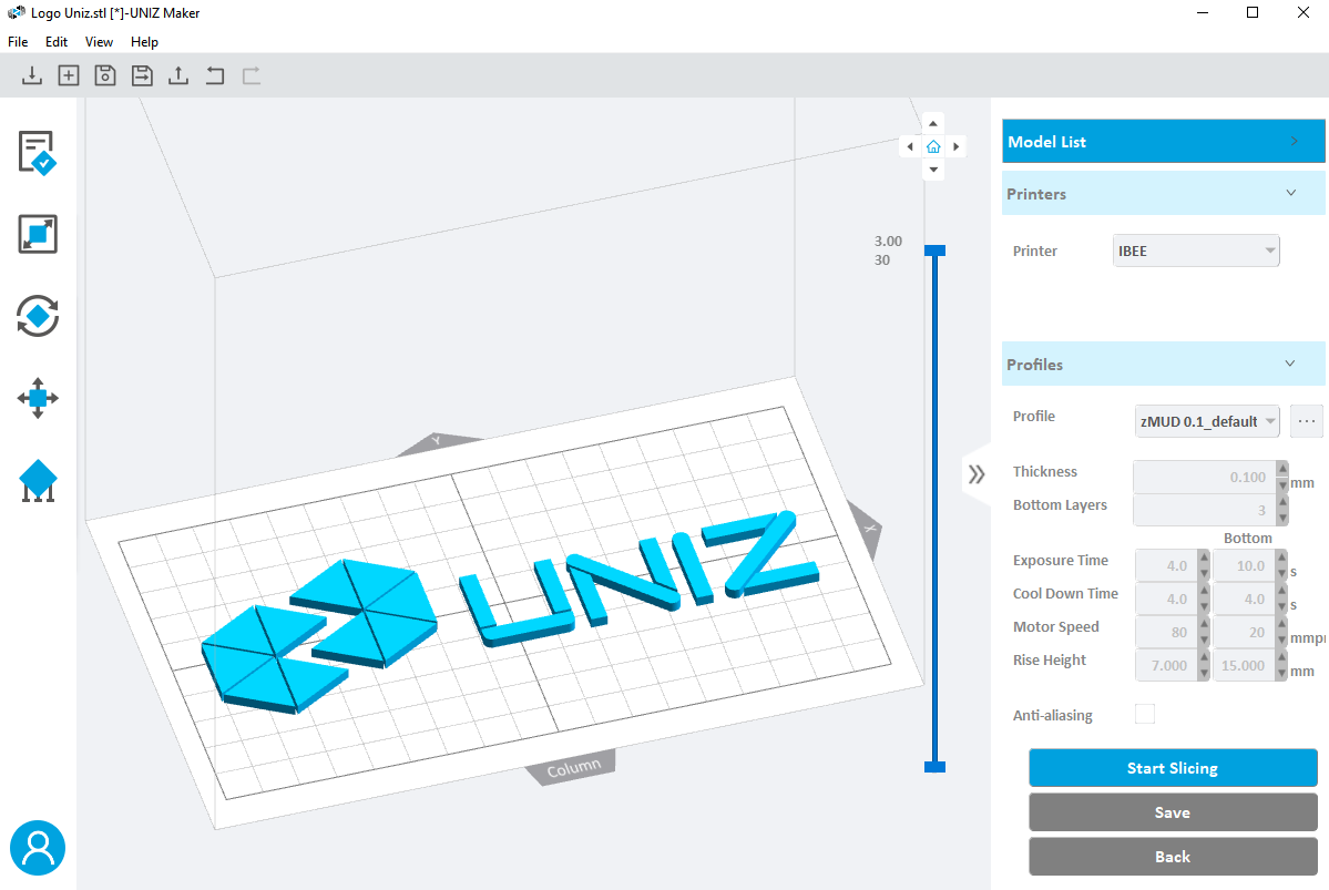
There are four parts in the interface.
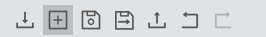
1. Menu and toolbar
Menu
File: Create, open and save projects, load and export models, and modify configuration files.
Edit: Undo/redo operations, select all, deselect all, duplicate, mirror, delete selected, one-click printing, size, rotation, position, supports and other editing functions.
View: Switch different views of your model; show or hide the model manipulator, toolbar, and right toolbar; switch software display languages: Spanish, English, and simplified Chinese.
Help: View UNIZ Maker help, release notes, and allow you to check for updates.
Toolbar
Open: To open 3D model or slices. The supported file formats are: stl, obj, 3mf, amf, zprj, slc, zcode.
New Project: Create a new project(zprj).
Save Project: Save the loaded model as a project file (zprj).
Save Project as: Save the loaded model to another project file (zprj).
Expert STL File: Export selected models and its support to STL format.
Undo: Repeal one previous operation.
Redo: Remake one previous operation repealed by "Undo".
2. Left Toolbar
Provides common functions for the preprocessing of 3D printing:

- One Click Print: According to the preset parameters, the software will automatically rotate and place the model, then add supports to make it suitable for printing. Then the software will execute the slice function, and expert the slice file.
- Size: Modify the size of the selected model.
- Rotation: Change the orientation of the selected model.
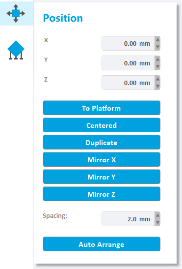
- Position: Edit the position of the model, center, duplicate, and mirror the selected model, and automatically arrange the model.
- Supports: Generate supports manually or automatically.
- Login: Users can login the software by using the account number registered on the official website.
3. Right Toolbar
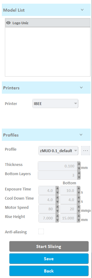
Model List: View the loaded model, modify the visibility and state of the selected model, and perform operations such as pasting, centering, copying, mirroring, and deleting the selected model.
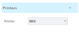
Printers: Select printer type. Different printers have different printing size and accuracy.
Profiles: select a preset slice profiles; manually adjust slice parameters, slice the model, and export slice files.
4. 3D Model Viewer
The interactive window is composed of three parts: the operation area in the middle, the view switch on the upper right corner, and the profile viewer on the right.
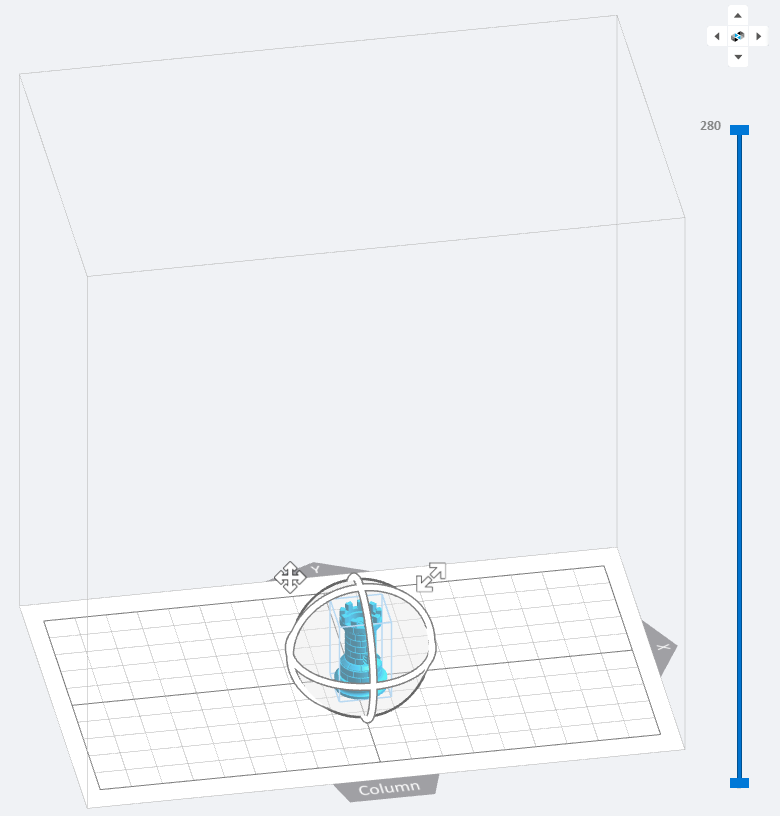
Operating Area
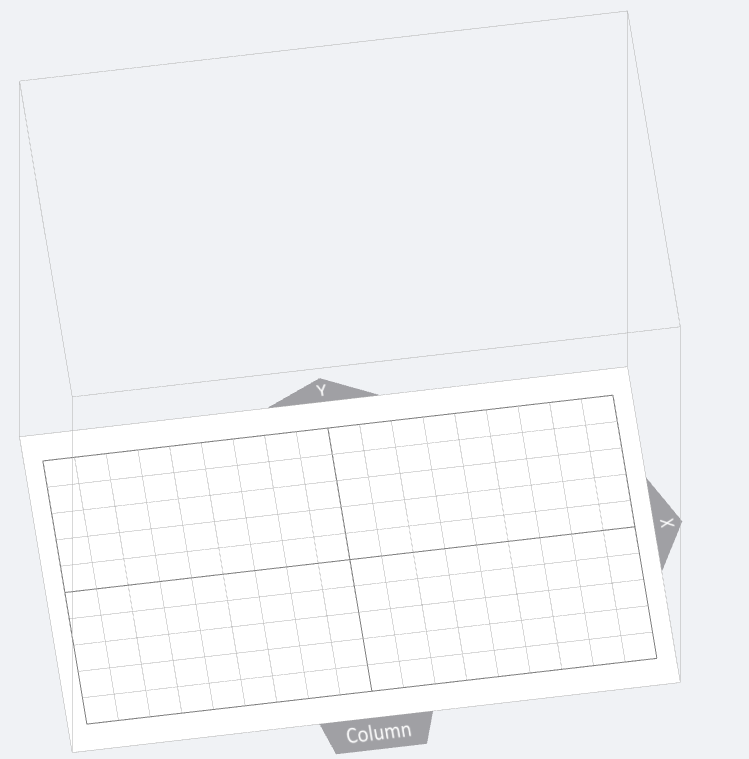
(1) Scope: The cube identifies the printing size and scope of the 3D printer. If the model is out of range, the excess part will be marked in red.
(2) Grid: The grid length and width are both 10mm, which is convenient for users to quickly evaluate the size and position of the model.
(3) Coordinate system: The coordinate origin of the 3D scene coordinate system is the grid center.
(4) X:X means the X axis.
(5) Y:Y means the Y axis.
(6) Column: The spatial position relationship between the model and the column on the printer.
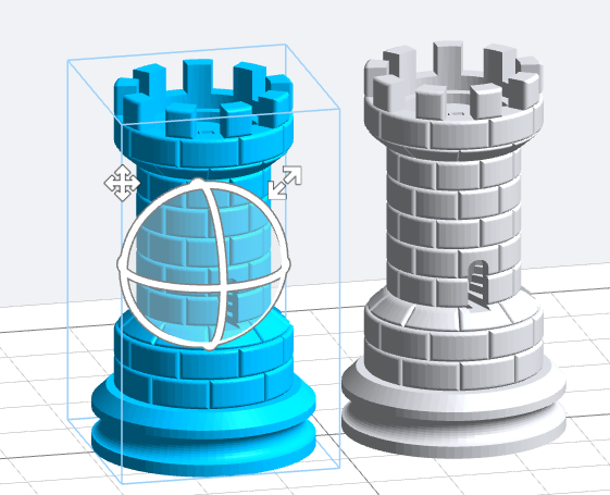
Manipulator:
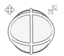
Select the model in the interface of position, rotation and scale. Manipulators will be suspended on the model.
Click and press  , drag the model to the target position to release.
Click and press  to change the size model.
Click and press the circle on the manipulator to drag and release, the model will rotate around the corresponding axis.
View Switch:

Switch the different view of the model.
Slice Viewer:
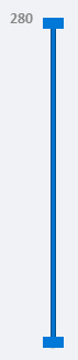
Drag the upper slider to cut the upper part of the model and observe the section;
Drag the lower slider to cut the lower part of the model and observe the section.
Select Printer Type
Open the UNIZ Maker, then select the printer type.
Load Model
To load one or more 3D models, you may either drag-and-drop into the 3D viewer, click  , or click “File” -> “Open” on the menu. File format supported: STL, OBJ, AMF, 3MF. The UNIZ Maker also supports project file(ZPRJ) and slice data(SLC, or ZCODE). SLC format slices can be converted into ZCODE format slices. Slice data in ZCODE format is convenient for browsing and checking.
Tip
If the 3D model is damaged , the system will prompt user whether to repair. If the user chooses to ignore it, the model may fail to print.
Switch View
Viewing your model from preferred angle will benefit model positioning. Press the right mouse button in the 3D window and drag it. If there is a selected model, the 3D scene will rotate around the center of the selected model. If no model is selected, it will rotate around the tray.
If you press the Shift key while dragging the mouse, the view will pan with the drag of the mouse.
Scroll the middle mouse button, and the 3D scene will zoom in and out of the view with the mouse position.
In addition, UNIZ Maker provides a threshold angle of view, the user clicks the menu "View" -> "Main View" / "Left View" / "Right View" / "Top View" / "Front View" or click  in the 3D window to quickly switch the view .
Model Selection and Shortcut
In the state of POSITION, ROTATION, SIZE, and SUPPORTS, the software supports two ways to select the model (clicking the left mouse button or dragging the box with the left mouse button), the unselected model is gray, and the selected model is blue color.
1.Select the model in the interface of position, rotation and scale. Manipulators will be suspended on the model.
- Position: click and press the position icon on the top left of the controller, drag to the target position to release.
- Rotation: click and press the circle on the controller to drag and release, the model will rotate around the corresponding axis.
- Scale: click and press the zoom icon on the top right of the controller to drag the zoom model.
2.In the interfaces of position, rotation and scale, right-click the selected model to pop up the menu, which specifically includes sub items such as “To Platform”, “Centered”, “Duplicate”, “Mirror X, Y, Z” and “Delete”. Select sub items and perform relevant operations.
One-Click Print
One-Click Print offers an option for automatically orienting, placing, generating support, slicing your models, which achieves the function of quick-printing.
Click  in the left toolbar to pop up the "One-click Print" box.
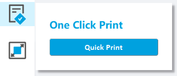
Click "Quick Print", software will execute sequentially:
- 1)Orienting
- 2)Laying out (multiple models)
- 3)Generating supports
- 4)Slicing
- 5)Expert slices
Notes:
A different orientation will be applied to models if click "Quick Print" for another time.
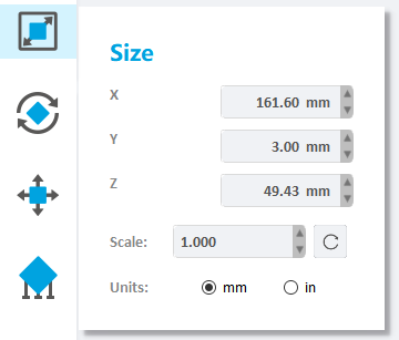
Modify Size
Press the Size Button  on the main tools will open following sub menu.
Once the Size tab is open, the activated object can be scaled freely by holding the left mouse button on the object and moving the mouse.
Select the model, the manipulators will be suspended on the model, click and press the zoom icon on the top right of the controller, and drag the zoom model.
The activated object can also be scaled by inputting X/Y/Z values in the field. Press Enter to apply changes. Users can also click the up and down button to change the size. The object will scale uniform in Uniform Scaling mode.
Modified scale: If a single model is selected, the model will be scaled according to the modified scale; if multiple models are selected, the scale of all models will be set to 1, and the modified scale will be scaled relative to 1.
Units: toggle between millimeters and inches.
TIP
Changing an object’s size will break previously generated supports and you will need to redo these.
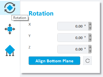
Change Orientation
Models need to be adjusted the angle according to its characteristics when printing, in order to obtain better printing results.
Click  in the left toolbar to enter the rotation interface.
Press the left mouse button on the selected model to drag, and the model will rotate freely.
Select the model, the manipulators will be suspended on the model. Click and press the ring on the controller to drag and release, the model will rotate around the corresponding axis.
The activated object can also be rotated by inputting X/Y/Z values in the field. Press Enter to apply changes. Users can also click the up and down button to change the angle.
Press the "To Align Bottom Plane" button, select the bottom surface on the model (the mouse turns into an orange line), and click the left mouse button to rotate the selected surface paste on the tray.
Notes:
Rotating a model along the X- or Y-axis supports will be removed.
Rotating a model along the Z-axis supports will not be removed.
Change Position
Pressing  will open following sub menu.
Once the Position tab is open, hold the left mouse button on the object and move the mouse to move the object freely in the X-Y plane. If the Shift key is held down, the object will be moved up and down along the Z-axis instead.
Select the model, the manipulators will be suspended on the model. Click and press  , drag to the target location to release.
The activated object can also be moved by inputting X/Y/Z values in the field, press Enter to apply changes. Users can also click the up and down button to change the position.
Click the "To Platform" button to modify the Z value of the selected model to zero, and the model will contact with platform.
Click the "Center" button to move the selected model to the center of the XY plane.
Click the "Copy" button, the selected model will be copied once.
Click the "Mirror X" button to mirror the selected model relative to the X axis.
Click the "Mirror Y" button to mirror the selected model relative to the Y axis.
Click the "Mirror Z" button to mirror the selected model relative to the Z axis
Click on the "Auto Arrange" button to rearrange the model according to the spacing and move it to the center of the build platform. Multiple clicks on the "automatic placement" button will result in different placement strategies for the model.
TIP
If the model is supported, modify the Z value and the support will be deleted.
Generate Supports
The principle of 3D printing is to print layer by layer If the part of the model is suspended, or the printed part couldn’t support the unprinted part,users need to add support.
Pressing  will open following sub menu. There are two ways for generating supports: Automatic Generation and Manual Edit.
Automatic Generation
The default support dialog is the automatic support interface, with three operation buttons at the top and support parameters at the bottom.
- Generate: Select the model to automatically generate supports using the parameters on the interface.
- Delete: Delete all supports on the selected model.
- Edit: Enter manual support mode.
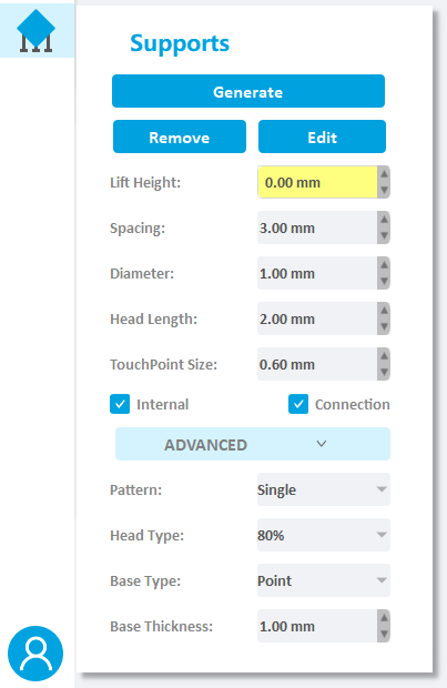
Firstly, user needs to select the model that needed supports, then set the parameters.
- Lift height: If the model needs to be fully supported, the model lifting height needs to be set, the recommended value is 5mm; if the model only needs partial support, users needn’t to set the lift height;
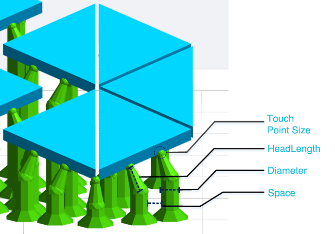
Set the Space, Diameter, Head Length, and Touch Point Size. - Internal support: If there is a suspension inside the model that needs to be added internal support, check this item;
- Support connection: If the support is very long, and the stability of the support needs to be strengthened, check this item;
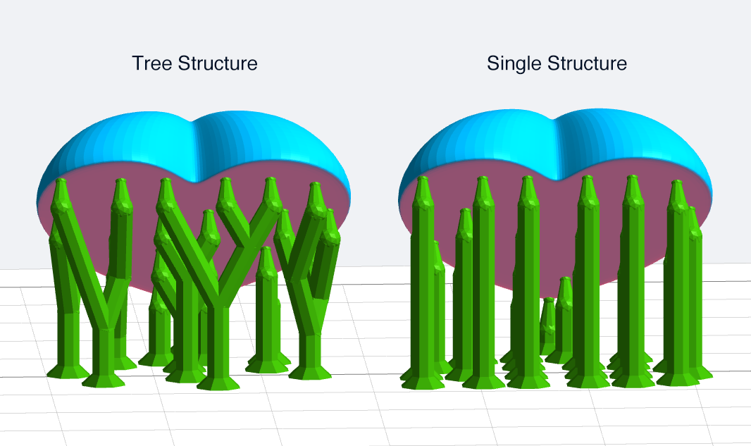
- Pattern: tree structure and single structure
- Head Type: The shape of the contact position between the support head and the model is a ball. The thickness of the connection between the support head and the ball differs with the setting of Head Type(50%~100%).
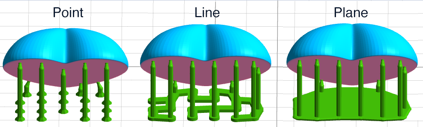
- Base Type: The software offers four base types: Point, Line and Plane.
- Base Thickness:The range of the base thickness is 0.5-2mm.
TIP
In the automatic support mode, the "Generate" and "Delete" buttons are only available after the model is selected.
Manual Edit
Click the "Edit" button on the automatic support interface to enter the manual editing. In this mode, users can add, modify and delete supports.
Add Supports
Move the mouse to the model, and if the green ball is marked at the mouse position, it means that the normal vector of the position is down and support can be added. Click the left mouse button to complete the new support work. If a red ball is marked at the mouse position, it means that the normal vector of the position is upward and no support is needed.
When you move the mouse, a white line will be displayed on the model. The white line is a contour line, which means all the points on the white line have the same z value. The white line can be used to easily find the floating point.
Select Supports
Mouse click and box selection are available to select the support.
Modify Supports
Click on the support head and drag it to the target position on the model and then release. The position of the support head will be modified.
Left-click on the support base and drag it to the target position on the platform to release, the position of the support base will be modified.
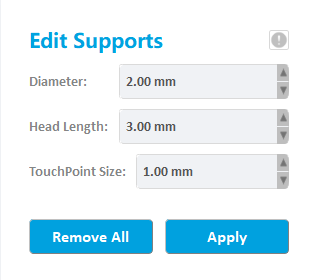
Select one or more supports, modify the support diameter, support head length and touch point size etc. the related properties of the model will be updated in real time.
Delete
Press the "Delete" button to remove the selected support.
Click “Remove All”, all the supports will be removed.
Slice
Slicing is the last and most important part of printing preprocessing. In the slice setting, the user needs to set the printing parameters, including layer thickness, exposure time, cooling time, motor speed, rise height, etc. The printing parameters affect the success rate of printing.
Slice Parameters
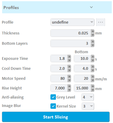
- Profile: It means the preset slice parameter list, the profile list belongs to the printer model.
- Thickness: Thickness is the thickness of each layer.
- Bottom layers: In order to ensure that the model can be firmly glued to the tray, the exposure time, cooling time, motor speed and lifting height are usually set separately for the first few layers.
- Exposure Time: is the exposure time of a layer in this segment.
- Cool Down Time: is the time interval from the exposure of the previous slice to the start of the exposure of the next slice. The LED light is off during this period.
- Motor speed: The motor controls the speed of the platform.
- Lifting height: defines the travel height of the platform after curing the layer.
- Anti-aliasing: Enabling Anti-aliasing will solve the Jagged edges problem and smoothen the edge of layer. This function can improve the surface smoothness of the model, and it provide nine gray level options from 0 to 8, please refer to "Anti-aliasing " for details.
- Image Blur: The goal of image blur is to reduce the number of lines and vertical artifacts on 3D printed model. This function can improve the surface smoothness of the model, and it provide two options of convolution kernel size of 3 and 5, please refer to the "Image Blur " for details.
Click the "Start Slicing" button, all models will be sliced using the set parameters.
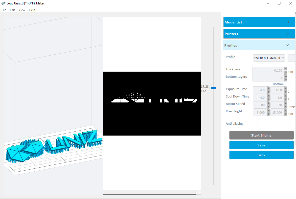
Slice Viewer
After the slicing is completed, the software will automatically switch to the slice preview window. Drag the sliding block up and down, and the left 3D window and 2D window will simultaneously display the slice at the height of the sliding block.
Slice export
Click the "Save" button on the right side of the slice preview window to pop up the save path dialog box, click the "OK" button to start exporting the slice.


